Motor-driven compressor → combustor → converging nozzle → thrust. Configuration after the Caproni Campini N.1 (1940).
1. Background: How a Real Jet Compares
A real turbofan has two airflow paths driven by nested concentric shafts, called a two-spool layout.
- The big front fan moves a huge mass of air slowly; most of it bypasses the core and produces about 80% of the thrust on modern engines.
- Behind the fan, the compressor, or second fan, does the opposite job: it squeezes a small mass of core air into a smaller, higher-pressure volume before the combustor. It is staged: a low-pressure compressor/booster on the same shaft as the front fan, driven by the rear low-pressure turbine, and a high-pressure compressor on a separate faster inner shaft, driven by its own high-pressure turbine behind the combustor.
- A real engine is self-sustaining: the turbines downstream of the combustor extract energy from the hot flow to drive the compressors.
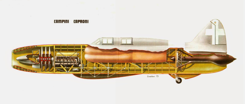
How this motorjet simplifies it: The Campini Caproni N.1 (above) solved the same problem using a piston engine to drive its compressor, replacing the self-sustaining turbine loop entirely. This build follows the same logic: an electric motor replaces that piston engine, driving a single centrifugal impeller instead of a multi-stage compressor. Because the shaft work comes from wall power rather than a turbine extracting energy from the hot flow, the cycle does not need to self-sustain, and there is no turbine in the exhaust path at all; the converging nozzle does the final job instead.
2. How It Works / Operating Principle
This is a motorjet, or thermojet, demonstrator. An electric motor replaces the power turbine of a real jet engine, so the thermodynamic cycle does not need to self-sustain. Wall power supplies the shaft work a turbine would normally extract from the flow.
- A motor-driven centrifugal compressor raises air pressure.
- A combustor adds heat at high static pressure, with fuel injected downstream of the compressor only.
- A converging nozzle converts that pressure into high exhaust velocity, producing thrust.
Operating logic: Hold high static pressure in the combustor for dense, stable burning, then convert that pressure to high exhaust velocity through the nozzle.
3. The Build (Current Physical Setup)
Drive
A brushed universal motor, directly spins the compressor impeller. It was chosen because it self-spins the cycle without needing combustion to sustain rotation.
Input / Intake
Ambient air is drawn in axially at the front through the motor/compressor inlet. The impeller pulls air in along the shaft axis and flings it radially outward.
Compressor
Centrifugal metal impeller, about 110 mm outer diameter. It discharges the compressed air into the chamber.
Airflow Out The Back Via 2 Holes
The compressed air exits the compressor into the combustion chamber through two outlet holes. These two holes are the primary combustion-air feed and are central to the whole design. Air enters the chamber, mixes with fuel injected downstream, burns, and exits rearward.
Combustor
Fuel is injected only downstream of the two air holes, mixed with the compressed air, and ignited.
Exhaust
A converging nozzle, or narrowing cone, accelerates the hot gas out the back to produce thrust.
Dropped on purpose: There is no downstream free turbine wheel. A free turbine would extract energy and slow the flow, costing thrust for no benefit, and it would be an unbalanced disk spinning in a hot stream, creating burst risk. The nozzle does its job instead.
Expected performance: Vacuum-impeller pressure ratio is realistically low, about 1.15–1.25:1 at zero flow and lower at the real operating point, and must be measured, not assumed. Expected cold thrust is on the order of a few newtons, or hundreds of grams-force. Rig vibration sets real resolution, so averaging via a load cell and logging beats chasing fine display digits.
4. Flashback / Blowback Control
On ignition, chamber pressure spikes and flame can try to climb back up the two air holes toward the motor. The fix is layered; no single measure is enough.
- Out-velocity beats flame speed: A flame can only travel upstream if the gas it is climbing moves slower than the flame propagates. Hydrocarbon/air laminar flame speed is sub-1 m/s. Size the two holes small enough that discharge velocity comfortably exceeds flame speed, so the flow physically blows the flame front back downstream. Smaller holes mean higher velocity, but only as small as the compressor can still feed without choking mass flow.
- Tangential injection / swirl: Aim the two holes tangentially, off-axis, not at each other. This creates a swirling vortex that anchors the flame in a central recirculation zone, held away from the inlet holes, while keeping high velocity right at the holes.
- Bluff-body flame holder: A small disc or cone on a stalk placed downstream of the two inlets creates a low-velocity wake that deliberately anchors the flame there, so it never wanders forward.
- Fuel placement: Inject fuel only downstream of the two air holes, into the established swirl. No fuel near the impeller means nothing to flash back to.
- Flame-arrestor option: A fine stainless mesh or perforated plate at or just behind the air holes acts as a flashback arrestor, using the Davy-lamp principle. It quenches any flame front trying to pass back through small passages. This is an optional belt-and-suspenders measure.
- Air staging: Treat the two holes as primary combustion air at the front. Any later downstream openings feed secondary/dilution air through the chamber wall further back to cool the burn without disturbing the upstream barrier.
5. Joining Hot Section to Cold Section
The interface where the hot combustor meets the cooler compressor/motor section is where cheap builds fail. The motor side needs protection from both conducted and radiated heat.
- Thermal break / air gap: Never bolt hot stainless directly to the cold section. Leave an air gap or insulating spacer so heat does not conduct straight back. Lengthen the conduction path where possible.
- Ceramic fiber insulation: Kaowool, ceramic blanket, or fireplace rope gasket can line the junction or wrap the combustor front.
- Radiation shield: A thin stainless shield or standoff between hot and cold faces blocks line-of-sight radiant heat.
- Hardware: Use stainless or steel fasteners only in the hot region. Never use aluminium or zinc, because they soften or melt.
- High-temp gasket: Use exhaust gasket sheet or fiberglass rope rated above 800 °C on the sealing face between sections.
- Slip-fit clamps: Stainless hose or band clamps let sections join and disassemble for tuning. A slip-fit tolerates thermal expansion far better than a rigid weld at the transition.
- Keep bearings cool: Ensure the motor bearings and windings stay well below their rating. The junction's whole job is to keep that heat from reaching them.
6. Materials & Max Temperature Ratings
| Material | Approx. Max Service Temp | Home-Manufacturability | Best Use / Notes |
|---|---|---|---|
| Aluminium | ~150–200 °C usable, melts ~660 °C | Very easy (cuts/drills/prints) | Cold section only (compressor housing). Never near flame. |
| Mild / carbon steel | ~400–500 °C sustained, melts ~1425 °C | Easy (cut, drill, weld) | Brackets, cold structure. Scales and weakens when glowing. |
| 409 stainless (ferritic, exhaust grade) | ~815 °C continuous | Easy (sold as exhaust tubing/sheet) | Cheapest hot-zone option; combustor and nozzle. |
| 304 stainless | ~870 °C continuous (~925 °C intermittent) | Easy (widely available sheet/tube) | Workhorse combustor and nozzle material. |
| 321 stainless (Ti-stabilised) | ~900 °C continuous | Moderate (less common stock) | Higher-temp combustor sections, weld zones. |
| Inconel 625/718 (nickel superalloy) | ~980–1000+ °C continuous | Hard (tough to machine, pricey) | Hottest tips/throat only if pushing temps. |
| Cast iron | Melts ~1200 °C | Moderate | Heavy; not ideal for thin combustors. |
| Ceramic fiber blanket (kaowool) | ~1260 °C | Very easy (cut with knife) | Insulation/lining, not structural. |
| Fiberglass rope / exhaust gasket | ~550–800 °C | Very easy | Sealing the hot-to-cold junction face. |
Material priority: Prioritise stainless exhaust tubing/sheet. It is already heat-rated, sold at auto parts stores, and the easiest path for a home build.
7. Variable-Area Nozzle (Future)
The goal is to vary the exhaust throat area to tune thrust and velocity, like a real jet's variable nozzle. Wiring and actuation control are out of scope here; this list is about potential parts, geometries, and heat-capable materials only.
Translating Plug / Centerbody
Recommended first attempt. A movable cone, or spike, on the centerline slides axially inside the convergent nozzle. Moving it changes the annular throat area. It has the fewest moving parts in the gas path, only one axial motion, and is easier to seal. Plug material should be 304/321 stainless or an Inconel tip, with a stainless guide rod running back to a cold actuation point outside the hot zone.
Telescoping / Sliding Sleeve
An outer convergent cone slides over an inner cone; relative position sets exit diameter. The geometry is simple, but sealing the sliding fit while hot is the challenge. Stainless on stainless with slip clearance allows for expansion.
Iris / Overlapping Petal Nozzle
Multiple overlapping stainless petals on pivot pins, driven by an external sliding ring/linkage, contract or expand the exit like a real afterburning nozzle. It is the most jet-like and the hardest to make, requiring precise overlapping petals, stainless pivot pins, and a cool external actuation ring. Use 304/321 stainless, with Inconel at the trailing tips if needed.
Material Notes
Keep all moving and sealing surfaces in stainless or nickel superalloy. Put pivots, rings, and linkages as far from the flame as geometry allows. Allow generous clearances for thermal expansion so nothing seizes when hot.
8. Safety Guards
- Flame backsplashes into motor: Covered by layered flashback control in Subsection 4: high out-velocity, swirl, bluff body, downstream-only fuel, and optional mesh arrestor.
- Start sequence, non-negotiable: Airflow on first, with compressor running and cold flow established. Ignition lit second, with the igniter energised before any fuel. Then introduce steady, metered fuel. Never fuel first; pooled liquid fuel lighting all at once can rupture a sheet-metal chamber.
- Pressure safety gate: No combustion attempt until cold-flow static chamber pressure is measured with the engine running and unlit. This confirms the compressor holds a positive pressure margin versus combustion backpressure and gives the real discharge velocity for flashback sizing.
- Fire precautions: Keep a fire extinguisher and fuel shutoff within reach, clear the test area, avoid aluminium/zinc anywhere hot, and keep everything stainless or steel in the hot zone.
9. Next Steps / Roadmap
- Measure cold-flow static chamber pressure, the safety gate, before any fire.
- Confirm positive pressure margin versus expected combustion backpressure.
- Acquire instrumentation: RC thrust stand (~49 N / 5 kgf range), digital manometer rated above expected chamber pressure, and load cell with data logging.
- Finalise and drill the two tangential air holes; fit the bluff-body flame holder downstream; add optional mesh flashback arrestor.
- Build and insulate the hot-to-cold junction using a thermal break, ceramic fiber, stainless hardware, and high-temp gasket.
- Dry-rehearse the start sequence; test ignition before introducing fuel.
- Run the first lit test; log thrust and chamber pressure.
- Prototype the variable nozzle, starting with a translating plug/centerbody.
Academic Inquiry: Verifying Conservation of Mass (ṁ = dm/dt)
Using the engine’s airflow to experimentally confirm the continuity equation, then produce a formal report with full error analysis.
Aim
I am using my motorjet’s measured airflow to test the law of conservation of mass. For steady, one-dimensional flow, mass cannot accumulate inside the engine, so the mass flow rate must be the same at every cross-section:
My aim is to measure ṁ independently at the inlet and at the nozzle exit, show that the two values agree within experimental uncertainty, and report a single best estimate of ṁ with its uncertainty. I will treat the law as confirmed if the difference between the two stations is no larger than the combined measurement uncertainty.
Theory I will establish
I will derive continuity from conservation of mass applied to a control volume around the engine. Starting from
and imposing steady flow (∂/∂t = 0), the storage term vanishes and I am left with mass in = mass out, i.e. ṁ1 = ṁ2. I will obtain the density at each station from the ideal-gas equation of state,
and the flow velocity from a pitot measurement of stagnation minus static pressure. Where the Mach number is below about 0.3 I will use the incompressible form,
and where it is 0.3 or above I will switch to the compressible relations,
I will always compute the Mach number first to justify which velocity model applies. As an independent check I will relate the result back to thrust through
which, for a near-perfectly expanded nozzle (pe ≈ pamb), reduces to F ≈ ṁ⋅Ve and gives a momentum-based estimate of ṁ to compare against the ρAV values.
Measurement stations
I will define Station 1 at the inlet/bellmouth, where the velocity is low and the geometry is clean, and Station 2 at the nozzle exit. I may add an optional station at the combustor inlet. I will record the role of each station so the mass balance between them is unambiguous.
Apparatus I will use
I will instrument each station with a pitot-static probe (or separate total and static pressure taps) read by a digital manometer or differential pressure transducer, and a type-K thermocouple for temperature. I will measure each station’s diameter with calipers, log motor speed with a tachometer, and capture thrust on an RC thrust stand with a load cell and data logger. For the later hot test I will measure fuel mass against time with a scale or flow meter.
Geometry
At each station I will measure the diameter D and compute the cross-sectional area as
recording the resolution of the measuring instrument so I can carry it into the error analysis.
Confirming steady flow
Because the whole derivation depends on steady operation, I will log RPM and the station pressures as a time series and confirm they are constant over the sampling window before I record any data. Continuity only holds when ∂/∂t = 0.
Procedure
I will run the safety gate first, measuring the cold-flow static chamber pressure with the engine running but unlit, and then perform the cold (unlit) test before anything else. The cold run is the cleanest proof of pure continuity because no fuel mass is added, so I expect ṁin = ṁout exactly. At each station I will take a pitot traverse, recording ps, p0 and T at several radial points rather than a single centreline point, since the velocity profile is not uniform. I will also log ambient pressure and temperature, and I will repeat each run several times (N ≥ 5) to support a statistical treatment.
Calculations I will perform
For each measured point I will compute the density ρ = ps/(R⋅T), the dynamic pressure q = p0 − ps, the Mach number, and then the velocity V, before forming the local mass flow ṁ = ρ⋅A⋅V. To account for the non-uniform profile I will area-average across the traverse,
I will then compare the inlet and exit values directly and also against the thrust-derived estimate.
Error and uncertainty analysis
I will propagate uncertainty through every formula using the root-sum-square (partial-derivative) method:
From the repeated runs I will compute the mean, the sample standard deviation s, the standard error s/√N, and a Student-t confidence interval appropriate to the small sample size. I will then combine the systematic (instrument) and random uncertainties in quadrature to give a total uncertainty U for the mass flow at each station.
Validation criterion
I will form the residual between the two stations,
and its uncertainty,
and I will conclude that conservation of mass is confirmed within experimental error if
For the hot test the criterion becomes |ṁout − ṁin − ṁfuel| ≤ the combined uncertainty.
Hot test, later
Once the cold continuity result holds, I will repeat the experiment with combustion, following the start sequence of airflow first, ignition second, and metered fuel last. In this case I will measure the fuel mass flow
and include it in the balance, since the exhaust now carries the air mass plus the added fuel mass.
Departures from the ideal
In the discussion I will address the real-world effects that bias the result: non-uniform velocity profiles, pitot misalignment, any residual unsteadiness, heat loss, and compressibility once the Mach number exceeds about 0.3. Using the propagation terms as a sensitivity analysis, I will identify the dominant source of uncertainty and state which measurement I would improve first.
Toward the written report
Finally I will write the formal report, structured as: abstract; theory with the continuity derivation and supporting equations; apparatus; method; raw data tables; one fully worked sample calculation followed by tabulated results; the error and uncertainty analysis; results giving ṁ ± U at each station and the residual against its uncertainty; a discussion of whether the law was confirmed within error and what dominated the uncertainty; a conclusion; and appendices holding the calibration data, full data set, and the propagation algebra.
Status: planning phase. Cold continuity test to be run first as the primary proof; hot test and full written report to follow.