Check Out My Projects
Every card opens the full write-up: notes, photos, and the lessons that came with them.
Electron Cloud Chamber Final Write-Up
Electron Cloud Chamber
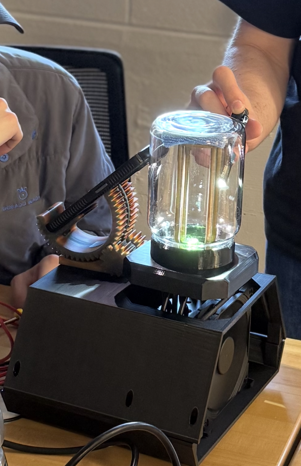
For our final project, my team and I created an electron cloud chamber, which is essentially a visual teaching tool for particle physics and visualizing an abstract concept. The whole reason we chose this project is because science classes can very quickly move into topics that are too small or too fast to actually see. That makes the topic feel distant, even when the physics is happening around us constantly. Our goal was to make a device that lets students see particle paths with their own eyes, instead of only hearing that ionizing radiation exists.
From the start, we tried to judge the chamber by a few concrete goals: it needed to be compact and portable, produce consistent results, have educational value, stay low-cost enough to replicate, and require minimal user involvement. Those goals mattered because this was not supposed to be a cloud chamber that only worked for us after a lot of tinkering. Ideally, it should be something an educator could bring out, turn on, explain, and use to get students interested in the natural sciences.
Target User
Educators, with students as the audience. The device needed to be easy to demonstrate and interesting to observe.
Core Effect
A temperature differential, alcohol vapor, and controlled environment make normally invisible particle paths visible as tiny droplet trails.
Final Deliverables
A Peltier-cooled chamber using a glass enclosure, PETG support hardware, and an open-source Instructables guide.
Physical Prototype
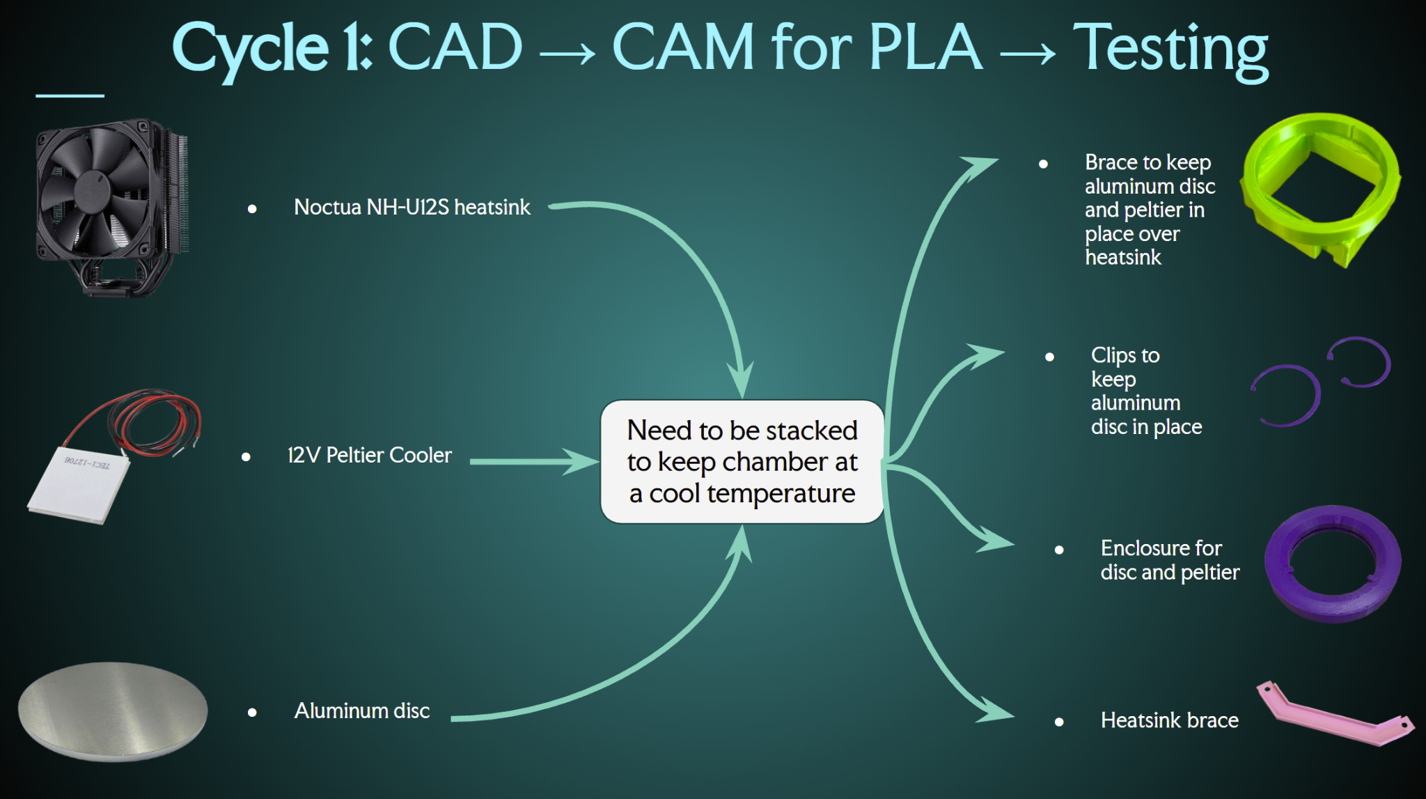
Our final physical prototype came out of four iteration cycles. The first build used a single TEC1-12709 Peltier module between an aluminum cold plate and a heatsink with a CPU fan. This version helped prove the basic stack could function, but it was not yet creating a favorable environment for viewing tracks. The temperature differential was too small for strong supersaturation, which we attributed to a poor seal and not enough thermal paste.
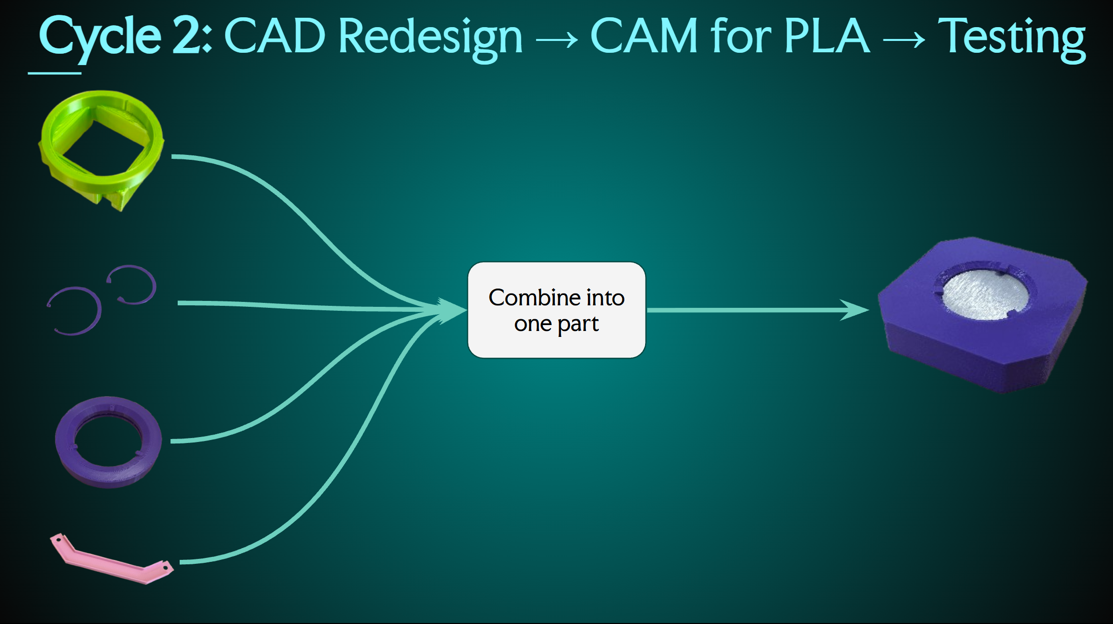
Cycle 2 combined several printed brace parts into one piece and shifted the testing from basic assembly toward measurable cooling performance. This is where thermal paste and current draw became useful variables, because both showed that the chamber depended on strong contact between the Peltier, plate, and chamber environment.
| Amount of Thermal Paste | Plate temp. |
|---|---|
| No paste | About 3 C |
| Minimal - pea size | About 2 C |
| Moderate - dime size | About -15 C |
| Lots - heatsink covered | About -25 C |
| Lots w/ chamber - Peltier + CPU fully covered | About -40 C |
| Current Supplied to Peltier | Reached Peltier Temperature |
|---|---|
| 4 amps | About -15 C |
| 5 amps | < -30 C |
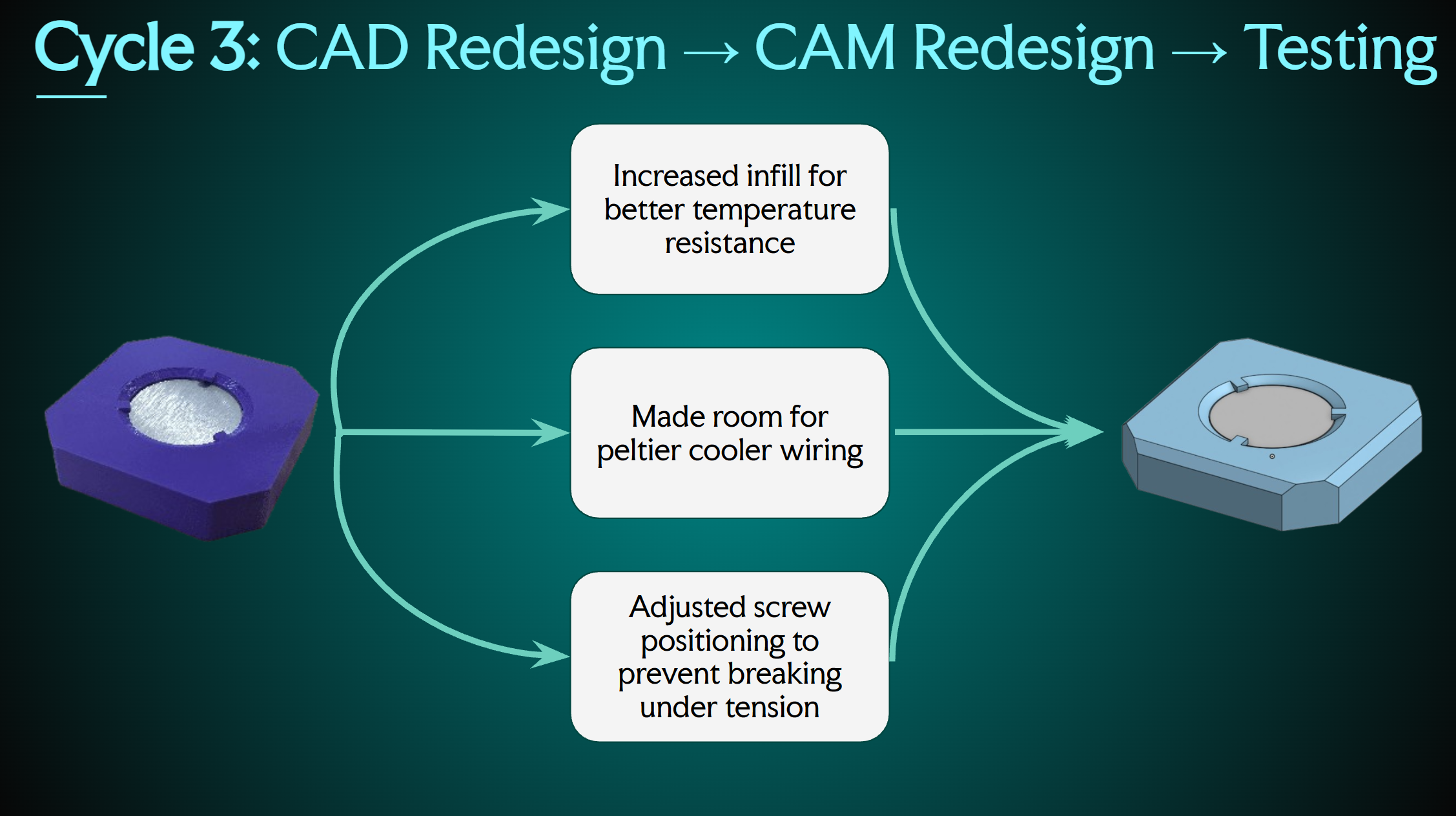
Cycle 3 focused on making the design easier to fabricate and less awkward to assemble. We moved from several 3D printed pieces to two main printed pieces, increased the infill for better temperature resistance, made room for the Peltier wiring, and adjusted the screw positions so the brace would not break under tension. We also moved from an acrylic enclosure idea to a glass one, using an upside-down Yankee Candle jar so we could avoid another custom fabrication step.
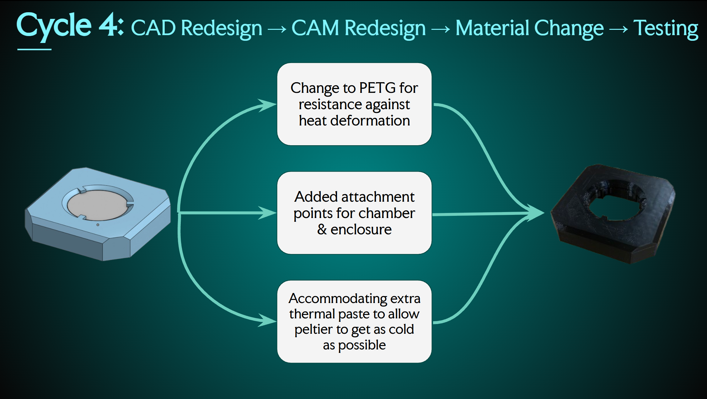
By cycle 4, the final version finally met all of our goals. We switched the support material from PLA to PETG, added attachment points for the chamber and enclosure, made room for extra thermal paste, printed a stand for the isopropanol rag, and added finger clearance so the brace could be taken apart without tools. Overall, this was the point where the chamber started to feel like a real device instead of a collection of tests.
Presentation Deck
The presentation deck below shows the full story of our project, including the problem definition, user research, major design pivots, prototype cycles, live demo explanation, GitHub repository, and future improvements.
PDF Presentation Final Electron Cloud Chamber Slides Open the actual presentation deck and scroll through the slides.Instructables Guide
For the open-source guide, we published the build as an Instructables project so the chamber instructions, materials, assembly steps, and testing notes are easy to follow in one public place. The goal is that another student, teacher, school, or lab could open the page and understand how to start without needing us to explain every part in person.
The Instructables page walks through the completed Peltier-cooled electron cloud chamber and keeps the project focused on accessible, reproducible particle physics instead of hiding the build behind hard-to-find resources.
Instructables Link
https://www.instructables.com/Peltier-Cooled-Electron-Cloud-Chamber/
Final Reflection
Overall, my biggest takeaway from this project is that making something work once is very different from making something useful for another person. At first, it was easy to focus only on whether the Peltier could get cold enough, or whether the chamber could show particle paths at all. However, the more we iterated, the more I realized the actual design problem was making the chamber reliable, explainable, and approachable for someone who did not build it.
I also think the project was helpful because every issue forced us to connect the user, the physics, and the fabrication. Poor sealing, too little thermal paste, awkward printed geometry, and an inconvenient enclosure were not separate problems. They all affected whether the chamber could reach the right environment for supersaturation and whether a user could actually operate it and learn from it. The switch to PETG, the glass enclosure, and the extra thermal paste were all small changes individually, but together they made the chamber much closer to the educational tool we originally wanted.
Moving forward, there are still clear improvements I would make. I would want a more precise housing that is portable but still large enough to keep the temperature stable, a dedicated power supply so the device does not require constant rewiring, a cleaner illustrated build guide, and eventually a sub-$100 version of the bill of materials. The final prototype succeeded, but these changes would make the project more realistic for smaller departments, personal builders, and teachers who simply want to introduce students to abstract ideas in a more concrete way. Furthering the skills we have to explore the "invisible."
Overall, this project showed me that the strongest design choices were the ones that made the science easier to see and those with the user in focus. The chamber is interesting because it makes particle tracks visible, but it becomes valuable when that visibility helps someone ask a better question than they had before using it.

Figure 1.1 (Click the image to view fullscreen)
1. Project Overview
My team's project focuses on a Peltier-cooled diffusion cloud chamber intended to function as an educational teaching tool. Rather than serving only as a device demonstration, the chamber is meant to create a classroom experience in which students can directly observe evidence of ionizing radiation and connect that observation to a physical reality.
My team and I chose this direction because particle physics can feel unintuitive, uninteresting, and difficult to access when students are asked to imagine a phenomenon they cannot normally sense; coupled with our personal interest in the discipline. Making radiation tracks visible to the human eye offers a more concrete way to introduce the topic and gives students a reason to observe, question, and discuss what they are seeing. The overall hope is that it inspires students to explore the fascinating world of particle physics further.
2. Research & Problem Framing
Problem Statement
This project addresses a common issue regarding certain academia, being the lack of a drawing and educationally valuable way to help students visualize non-intuitive topics. This can range from a topic within anthropology, such as the massive scale of city population to that of our focus, particle physics. Our project will visualize the passage of ionizing radiation in the atmosphere, here, on Brandeis's campus. The goal is to develop a device, electron cloud chamber, that makes an invisible phenomenon visible. We hope to make this topic more accessible by presenting it in a form that supports classroom teaching, discussion, and conceptual understanding.
Background Framing
Our approach for the project is framed around the diffusion cloud chamber, rather than around detection alone. The chamber works by creating a supersaturated alcohol vapor to flood the enclosed atmosphere. Within the chamber will be a great temperature differential between the top and surface of the base, the base being around -30 celcius. That temperature gradient creates the sensitive region where particle tracks become visible. In general, the idea is about visualization, but for those interested in the physical phenomena; the trails are visible because a charged particle passes through a supersaturated alcohol vapor in the cloud chamber and ionizes the gas along its path. The vapor then condenses onto those ions, forming tiny droplets. Those droplets line up where the particle traveled, so you can see a visible trail of exactly that particle's path. For the basic educational demonstration, natural background radiation should be enough to create visible trails, meaning nothing special needs to be placed inside the chamber for the core effect to appear. However, I have included an image below that represents what happens when something of greater emission is placed inside the chamber (an alpha emitter).
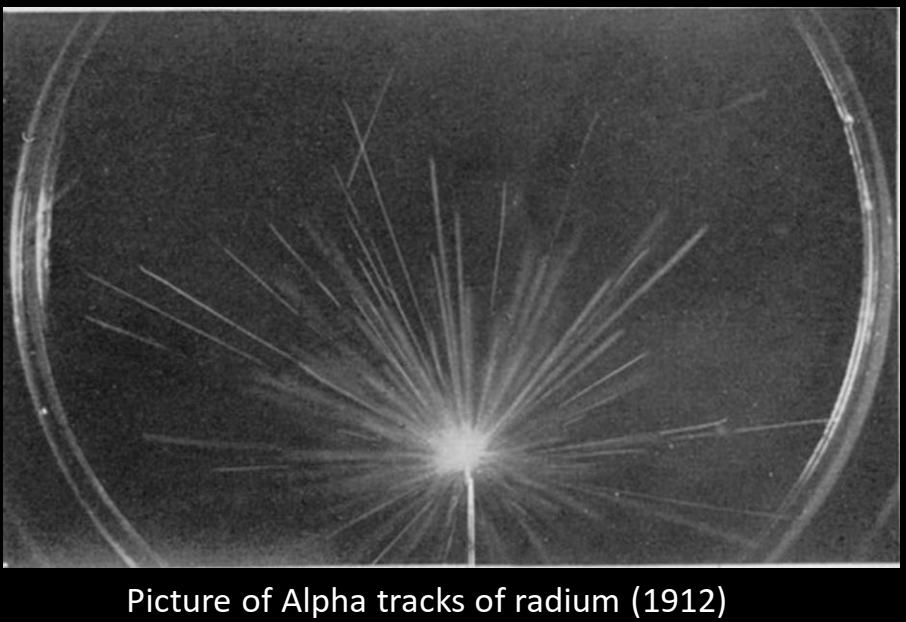
Figure 1.2 (Click the image to view fullscreen)
Source: Cloudylabs, "The first particles detectors"
The emphasis is on the chamber as an educational system. The value of the demonstration comes from allowing students to see direct visual proof that atmospheric radiation exists, notice that different particle tracks may appear different, and begin asking what is visible, what can be inferred, and what still cannot be directly seen. This can give rise to questions regarding how we can alter these paths, how to induce a longer path, as well as, the limitations of the device. That is how we plan to balance educational value with accessibility and usability for anyone to participate in understanding.
User / Customer Profile
- The primary users are any individuals who are struggling to understanding something that feels abstract and make it concrete. Specifically aimed towards students and possibly researchers. The idea is that they can come to conclusions and form hypotheses about this invisible concept independently using the device.
- The secondary users are physics' majors. Although, they could benefit from the demonstration, this is mainly a focus on helping those who cannot visualize the invisible in anyway; therefore a physics major studying these concepts might already have a good idea of the abstract in a "concrete" form via mathematics. However, as mentioned the device can still benefit these individuals as they too, cannot often see this phenomena with the human eye. If they could, then they would be a superhero.
- The educational goal is to help students build interest, ask questions, and connect what they observe as physical reality to the abstract.
- The chamber will teach students to make observations of the now visible particles and convert those observations into understanding, rather than overwhelm the users with engineering details and the complex underlying quantum mechanics. As mentioned, the idea is to help individuals understanding the power of visualization when understanding an abstract concept.
3. Problem Definition & Brainstorming
Thematic Design Tensions and Themes
- One major challenge is creating interest in something that students cannot normally sense and connecting this topic to the idea of accessibility for all users.
- The project has to balance functionality, portability, consistency, aesthetics, and educational value.
- Another hurdle is the balance between system autonomy and the amount of interaction users should have. Ideally, we want the users focus to be on the chamber not the controls. Our plan is to build the device with a simple plug and play interface.
- The chamber also raises the notion of showing versus explaining. Although, we want to show the user this phenomena, they will not always understand what the importance is. As the builders we will add an interface that briefly introduces the user to the concepts we hope to convey.
- Mathematics and physical law both need to be incorporated in a way that feels meaningful rather than forced onto the users; as we assume they are not familiar with the complexities of the topics. In general, we can approach this from a fabrication stand point alone with zero quantitative analysis. On the flip side we can also calculate the amount of voltage necessary, coupled with the efficiency of the heat sink, without forgetting the impact of density of saturation...and very quickly we lose sight of our original intent. This fine line between over-explaining and educational substance will have to be addressed carefully and presented with the user in mind being someone not currently familiar with the concepts.
Design Themes Summary: Accessibility to the invisible, educational value, portability, consistency within the device, autonomy balanced with user interaction, and deeper scientific explanation beyond spectacle without over-explaining to a uninformed audience.
Insight Statements about Design
- Students struggle to engage with ionizing radiation because it is normally invisible and difficult to connect to everyday experience.
- A successful classroom cloud chamber must do more than function physically; it must also balance cooling performance with portability, consistency, and educational clarity.
- Too much automation may reduce learning, while too much user control may reduce reliability.
- The educational power of the chamber comes not only from showing tracks, but from helping students ask better questions about what those tracks mean.
- The chamber is strong as a teaching tool as it connects direct visual experience to broader academic clarity.
Focused Questions
- How can we make ionizing radiation visible in a way that feels concrete and captivating to students?
- How might we design a cloud chamber that is compact and portable without sacrificing track visibility and consistency? How does design effect who can use it? Why?
- How might we balance automation with user interaction so the system is reliable but still educational?
- How might we use the chamber not just to show tracks, but to prompt deeper discussion of physics concepts and limitations? How do we move students past the "Whoa! Cool" stage, into forming hypotheses?
Selected Design Direction
The selected direction is a Peltier-cooled diffusion cloud chamber designed as an educational teaching tool. I chose this approach because it supports the core goal of making invisible radiation visible, while also allowing the project to be built around usability, safety explanation, and conceptual accessibility rather than engineering spectacle alone. At this stage, this should be read as the current direction rather than as a fully finalized design.
Figure 1.2 (Click the image to view fullscreen)
4. Storyboard
- The cloud chamber , pictured in Figure 1.3, then acts as the bridge between that invisible idea and the perceivable physical world, allowing the lesson to begin with observation rather than abstraction alone.
- The next step is explaining that the device is a diffusion chamber, which creates a supersaturated vapor by keeping the bottom very cold while the top remains warmer. It's crucial to begin the explanation post demonstration as we are focused on the connection not this specific phenomena necessarily.
- Once the chamber reaches that sensitive state and proper temperature differential, charged particles passing through the region leave visible condensation tracks, which the user will now see.
- At that point, students will begin asking questions about what they are seeing, why some tracks may appear different, and what can actually be concluded from the demonstration. And the most common, "is this safe?" Of course, the particles are there whether we visualize them or not, that is our whole point! Success!
- The instructor can then use the chamber to connect those visible trails to larger physics concepts instead of treating the demonstration as spectacle alone.
- The chamber's components can also become part of the explanation, since the build itself helps show how the conditions for visibility are created and give a brief introduction to circuitry.
- From there, the demonstration can lead into broader real-world or scientific visualizations and show that the classroom experience connects outward to larger contexts.
- The instructor also has an opportunity to address safety and misconceptions surrounding radiation, electricity, and the chamber's hot and cold components.
- The experience ultimately opens the door to deeper learning, including equations, interpretation, and broader particle physics ideas that grow out of what students have already observed.
- Finally, the last step the student will take is that when they tell all their classmates how incredible ionizing radiation can look! On a more serious note, the user can now express something that was once invisible, using concrete observations. Our hopes are that this promotes a welcoming introduction to less intuitive concepts
Our story begins with a classroom problem: a physics professor wants to introduce students to ionizing radiation, but the concept is difficult to make concrete because students cannot directly sense it.
Figure 1.3 (Click the image to view fullscreen)
Source: RS DesignSpark, "Peltier Cooled Cloud Chamber Part 2"
5. Current Design Direction
Our design direction is a Peltier-cooled diffusion cloud chamber. A similar approach has been taken using dry ice, however that is not user friendly. In the present system logic, stacked Peltier modules create the cold side needed for the chamber, an aluminum plate is part of the cold-side design, and the hot side must be actively cooled with a heat sink and CPU fan. A buck converter has also been discussed as one option for setting the Peltier voltage and keeping it stable, however, proved unnecessary. Overall, the design is trying to balance cooling performance, a stable atmosphere, and classroom usability.
The list below reflects the current documented direction rather than a locked final bill of materials. In general, the design will remain consistent but some parts may be removed or changed:
Current Documented Parts
- DC PSU
- CPU fan / heat sink
- stacked Peltier modules (pre-stackedd)
- aluminum plate 60mm diameter x 3mm height
- thermal paste
- temperature gauge
- wires
- fuse (undecided if needed)
- silicone insulation
6. Closing Reflection
The larger goal of this project is to make an abstract concept feel more concrete. Particle physics can be difficult to understand when students are asked to imagine a phenomenon they cannot normally see, so the cloud chamber gives them a more direct way to connect observation to the underlying physics. By making ionizing radiation visible in a classroom setting, the project can help turn a difficult topic into something more accessible, discussable, and real.
Prototyping and Testing
This section tracks the four prototype cycles we used to refine the cloud chamber's hardware housing.
Iteration Cycle 1
CAD -> CAM for PLA -> Testing
The problem statement for this project puts a lot of weight on making sure many individuals can access the materials required to make the cloud chamber and keep using it over time. Because of that, we framed our first prototype around a set of quantifiable goals that kept the build process fast, understandable, and repeatable.
- 3D prints fit their associated hardware without needing modification.
- Parts are all compatible with one another, and the Peltier brace can be built using screws without force or extra connection methods.
- Parts can be exposed to temperatures -30 C or colder for 10 minutes or longer without deforming, cracking, or breaking.
- The brace can be disassembled without breaking parts, using additional tools, or requiring a reprint.
- All parts can be printed on one PRUSA Mini+ build plate.
For cycle 1, only two of the five goals were met. This first version proved that the cooling stack could be organized physically, but it also exposed where the concept still failed once we moved from theory into an actual printed assembly.
The biggest issue was that the parts were not yet behaving like one fully resolved system. Even though some of the fit conditions were close, parts of the assembly were still relying on gravity instead of being directly secured to one another, so the first prototype was useful mainly because it showed us exactly what had to change next.
Iteration Cycle 2
CAD Redesign -> CAM for PLA -> Testing
- 3D prints fit their associated hardware without needing modification.
- Parts are all compatible with one another, and the Peltier brace can be built using screws without force or extra connection methods.
- Parts can be exposed to temperatures -20 C or colder for 10 minutes or longer without deforming, cracking, or breaking.
- The brace can be disassembled without breaking parts, using additional tools, or requiring a reprint.
- Parts can be printed on one PRUSA Mini+ build plate.
We checked off two new goals with iteration 2, but we also gave up two gains from the first version in the process. This redesign improved part compatibility and made the set easier to fit on one PRUSA Mini+ build plate, which moved the project closer to something more repeatable and practical to fabricate.
The tradeoff was access. Taking the aluminum disc out of the brace became less convenient than it had been before and could require either very small fingers or needle-nosed pliers, so cycle 2 taught us that making the structure tighter and more integrated could also make maintenance harder.
Iteration Cycle 3
CAD Redesign -> CAM Redesign -> Testing
- 3D prints fit their associated hardware without needing modification.
- Parts are all compatible with one another, and the Peltier brace can be built using screws without force or extra connection methods.
- Parts can be exposed to temperatures -20 C or colder for 10 minutes or longer without deforming, cracking, or breaking.
- The brace can be disassembled without breaking parts, using additional tools, or requiring a reprint.
- Parts can be printed on one PRUSA Mini+ build plate.
Iterations 2 and 3 were the closest to one another, but cycle 3 arguably moved us the furthest toward the version we actually wanted. We made room for Peltier cooler wiring, adjusted screw positioning to reduce breakage under tension, and changed the CAM approach so the printed part could better support the temperature demands of the chamber.
This was the point where the design started to feel much more buildable in practice. We kept the compatibility and one-plate fabrication gains from the previous version, and the added wire routing finally helped us resolve the hardware-fit issue without noticeably increasing the print footprint.
Iteration Cycle 4
CAD Redesign -> CAM Redesign -> Material Change -> Testing
- 3D prints fit their associated hardware without needing modification.
- Parts are all compatible with one another, and the Peltier brace can be built using screws without force or extra connection methods.
- Parts can be exposed to temperatures -20 C or colder for 10 minutes or longer without deforming, cracking, or breaking.
- The brace can be disassembled without breaking parts, using additional tools, or requiring a reprint.
- Parts can be printed on one PRUSA Mini+ build plate.
By the fourth and final iteration, we checked off the last two goals on the list. We had planned from the beginning to wait until the design felt stable before changing the material from PLA to PETG, and that switch finally gave the brace the resistance it needed against heat deformation and extended cold exposure.
The last redesign also improved attachment points and added better clearance for handling the brace during disassembly. At the same time, we adjusted the design to accommodate extra thermal paste so the Peltier could get as cold as possible without fighting the structure around it.
At this point, the cooling-support hardware finally met all five goals together. That made cycle 4 much more than a late-stage tweak; it became the version that tied together manufacturability, compatibility, durability, and day-to-day usability in a way that actually supports the final classroom cloud chamber build.
Assistive Writing Device
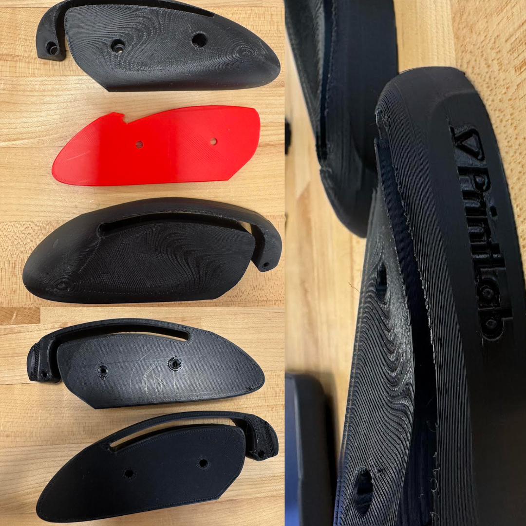
Figure 3.1 (Click the image to view fullscreen)
I decided to build this device based on its practical applications and similarities to an already widley used product. The assistive writing tool I printed from an open source design mimics the structure of a common computer mouse. This design is not only easy to hold for those with minimal strength in their fingers, but also allows the user to smoothly maneuver the device on most surfaces; as you would a computer mouse. The device was a three part print which required a small amount of hands on construction. The overall use-case for the device is to assist users with difficulty in writing by providing a stable point for the writing utensil and easy to hold control point.
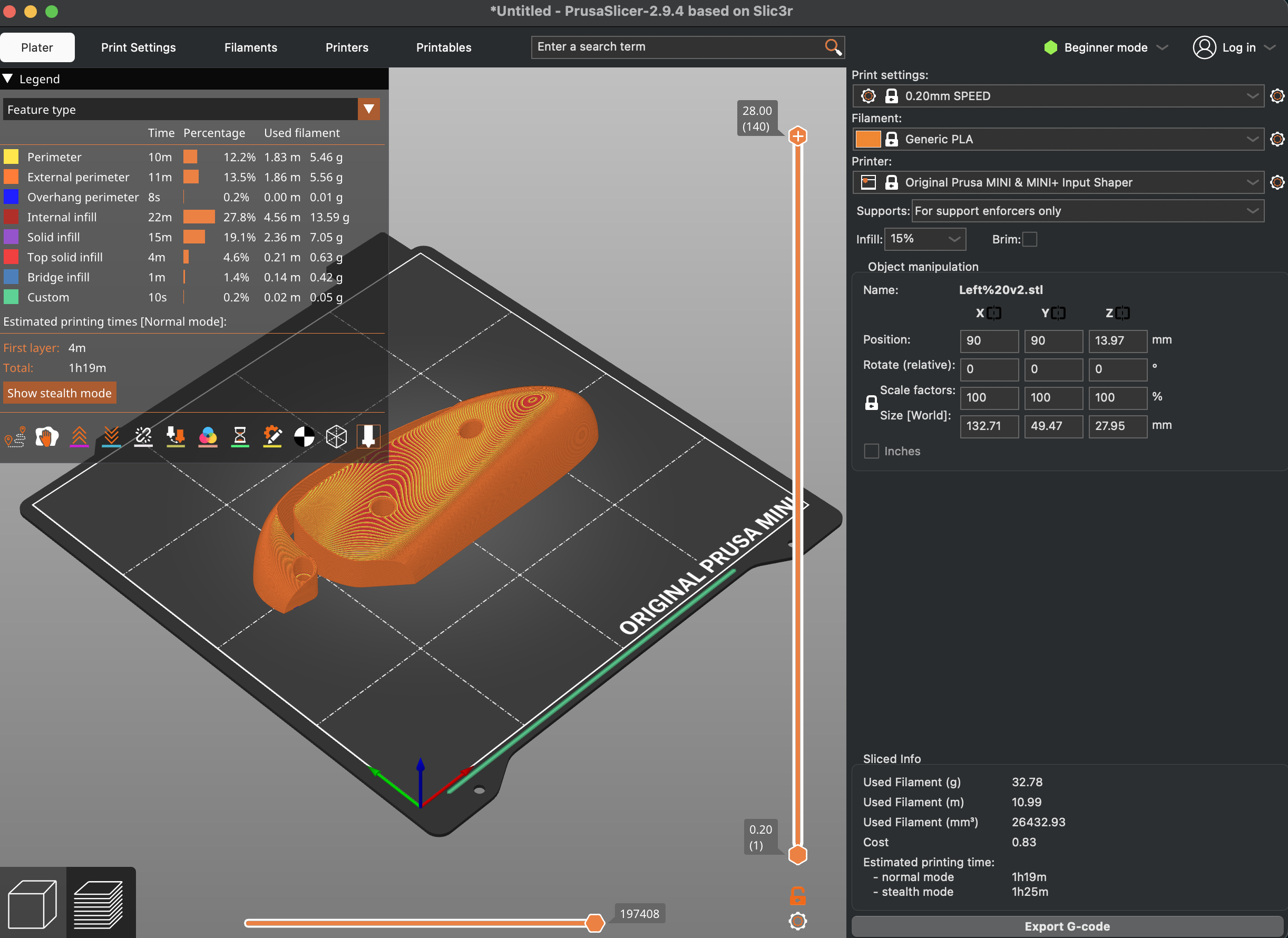
Figure 3.1 (Click the image to view fullscreen)
Settings Left Side (pictured above):
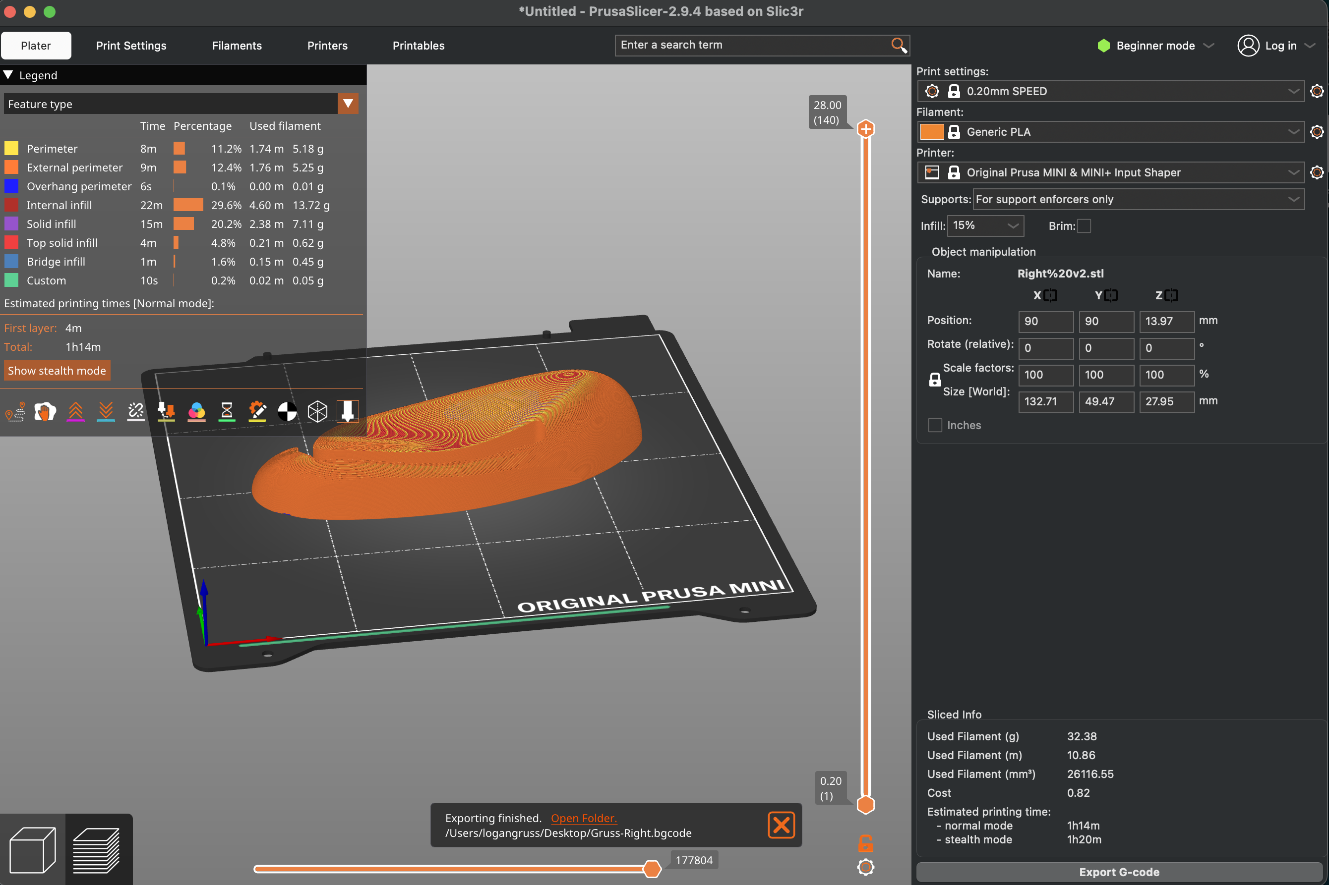
Figure 3.1 (Click the image to view fullscreen)
Settings Right Side (pictured above):
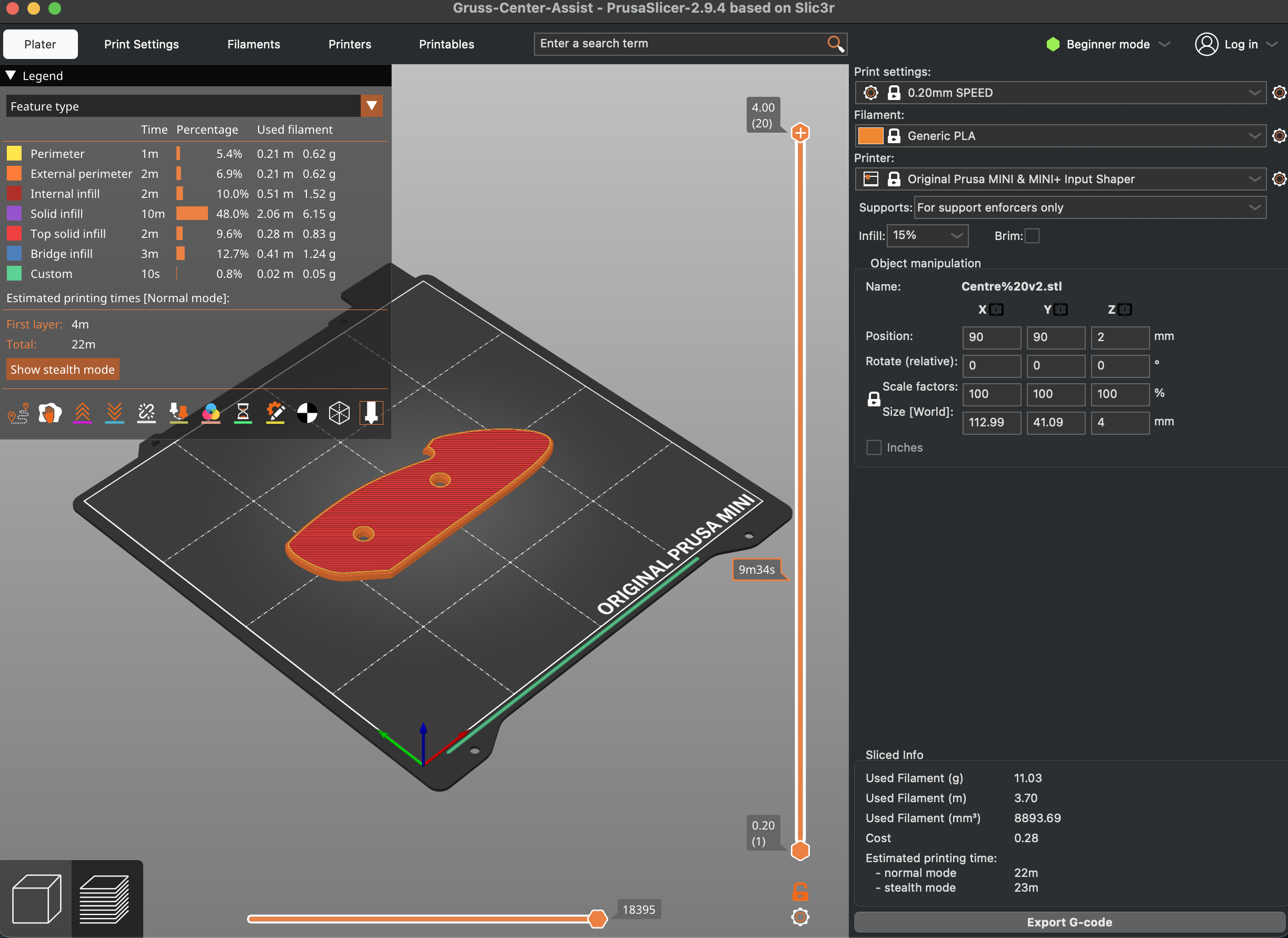
Figure 3.1 (Click the image to view fullscreen)
Settings Center (pictured above):
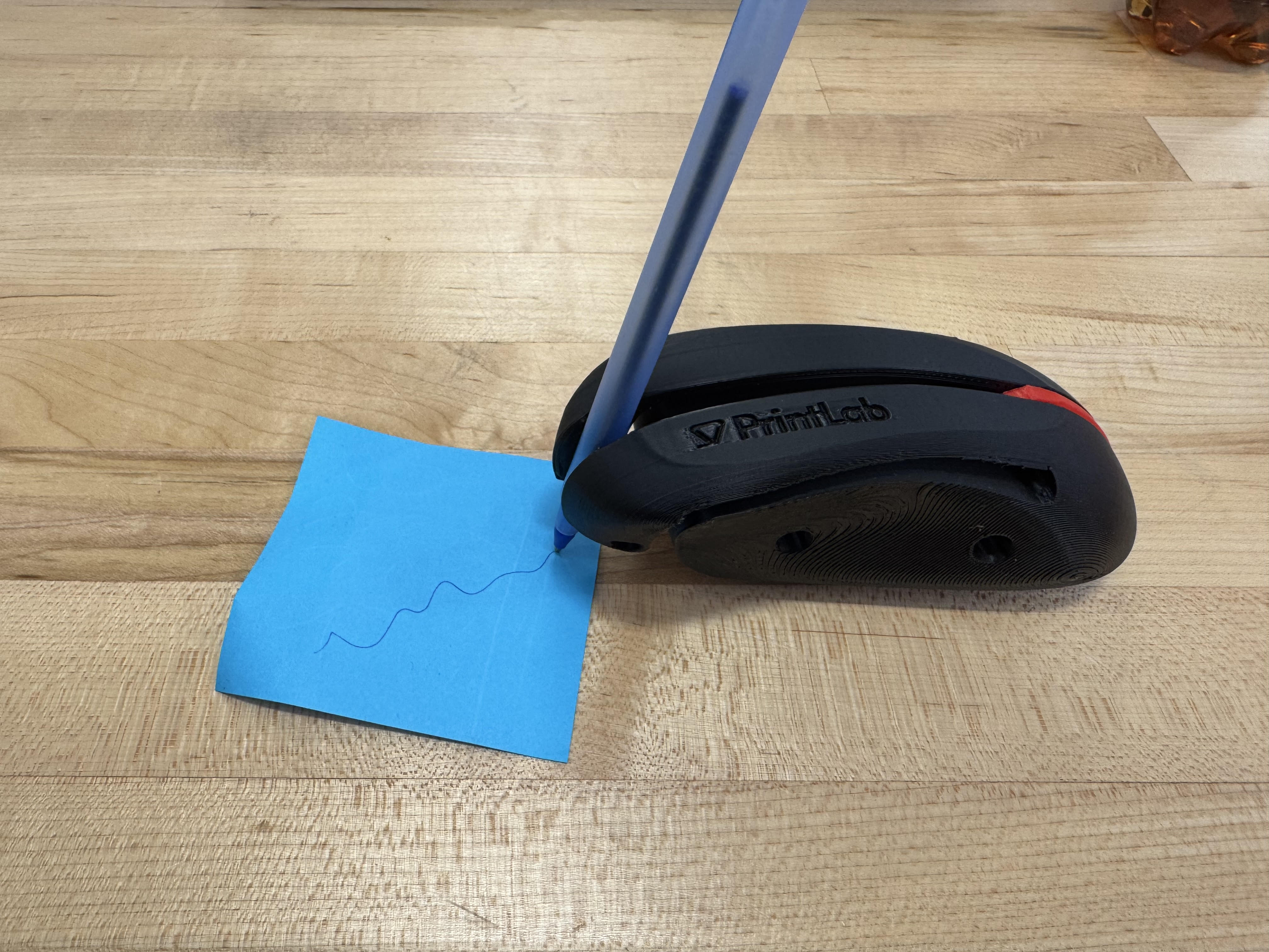
Figure 3.5
The completed product (Figure 3.5) requires about 2-5 minutes of manual assembly, where I was required to insert two M3 x 20mm screws into the sides. For the clamp that holds the pen, I also inserted another M3 x 20mm screw. The final build is sturdy and easy to move around on most traditional desktop surfaces. The size of the pen that the device can hold varries, but in general fits any writing utensil without a grip. Overall, my hopes are that this can help those struggling to grasp a thin object like a pen, as well as, create a stronger anchor point when writing.
Issues:
The left and right sides of the device had virtually no printing issues whatsoever. The only distortion was a slight fold in the area which the user would insert a screw. However, given the function of the hole, this should not be a major issue. When creating the center of the device I came across a much greater problem. When printing, the print began with a very thin layer of the base of the object but then was trapped in a loop moving from a point A to a point B over and over. This happened twice, until I replaced the (.bgcode). After that the print functioned normally. The cause of this issue seemed to be within the code I uploaded to the machine. I say this after a series of trial-and-error. I first examined the filament, which was properly aligned, I then ensured the plate was of correct height and the nozzle not clogged in anyway. After switching to a second printer, and having the same exact issue I deduced it was an issue with the file. After recreating and reuploading the file, the print succeeded. It is important to note that the filament could have been broken at a certain point when fed into the machine. This is unlikely though, given the same issue occurred on separate machines. However, moving forwards a slight "bend-test" prior to inserting the filament can ensure it has not accumulated too much water.
Line-Tracking Car
This was a joint venture between Ben Khayat and myself in which we explored a few different mediums for constructing a path following kit-car. The vehicle uses two sensors to determine the color change (from bright to dark) of the path and corrects accordingly. The ability to detect these changes, keeps the car focused on the dark electrical-tape path we created.
The kit we used came with all the needed components, including two sensors, motors, wheels, and essential capacitors and resistors (shown in Figure 4.1). We soldered on all the necessary components, which I detailed further below along with certain issues we had. Prior to our build, neither of us had had any experience soldering. The manual (linked here: https://m.media-amazon.com/images/I/A1lEYFXJO1L.pdf) gave thorough instructions with images, however, it did not provide much insight on the soldering process. For example, certain components required different strategies for making the solder joints. The manual, however, wrote all instructions the same regarding "how" to solder the components.
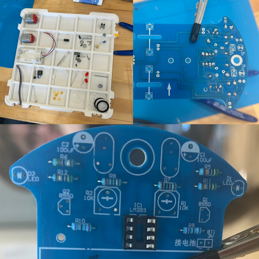
Figure 4.1 (Click the image to view fullscreen)
Constructing The Circuit Board
Prior to constructing the chassis for the car, we needed to solder the parts, shown in the tray above, to the circuit board. We found it helpful to organize our workspace prior to beginning. To best split the work load, we each soldered a few components and then the other would solder an equal amount until we were finished. On the first day, we were using an old soldering iron which downgraded the quality of each solder. In order to combat this, we were constantly tinning and cleaning our iron with iospropyl alchohol. Luckily on day two, we acquired a much newer iron, and therefore had cleaner solders and were no longer required to tin the tip each time. This is apparent in the top right photo in Figure 4.1, by the difference in solder quality. Besides capacitors, LEDs, resistors, components to set the intensity of correction, and other parts for our board, we also had sensors and motors. The sensors allowed for our kit-car to determine the intensity of color on it's left and right sides, which keeps it in line. These sensors would then drive power to either the left motor or right motor depending on what is needed to continue on the dark line. The two LEDs on the front-sides, indicate which wheel is recieving power. The angle of intesity the vehicle will take is dependent on a set of controls that we had to adjust until we were satisfied with the movement. For a turn of too great an angle could send the car off the track and it become "lost." I included a sketch of the dimensions of the board down below.
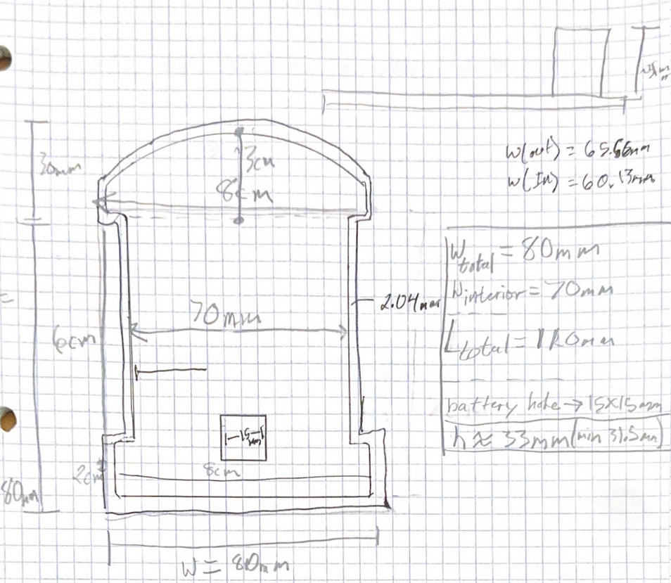
Figure 4.2 (Click the image to view fullscreen)
Dimensions:
Width (total)=80 mm
Width (interior)=70 mm
Length (total)=110 mm (30mm+80mm)
On/Off Slot=15x15 mm^2
Height= 31mm minimum
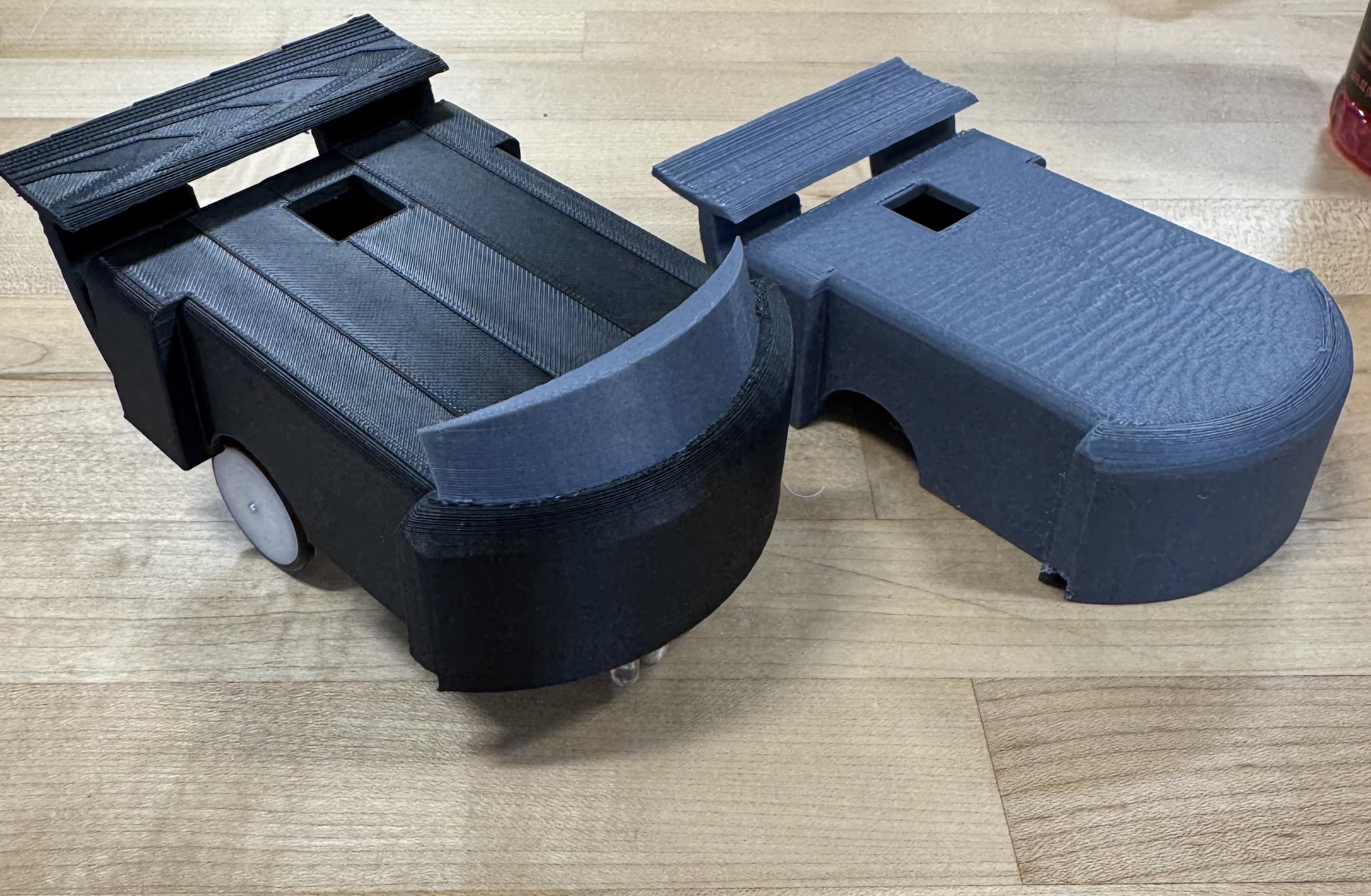
Figure 4.2 (Click the image to view fullscreen)
3D Printed Chassis
We decided to create two alternative prints for our project, working together in a shared OnShape space. We shared this responsibilty by adjusting and adding to the project as we both saw fit. The first, being the fully grey print in Figure 4.2, was a focus on scale and fit. In order to determine the proper dimensions for the print we used a caliper to find the length, width, and height of our car. It is important to also pay special attention to the front of the car, which was an arc instead of a flat bumper. By finding the radius of that arc, we easily scaled the front. The first print provided us with confirmation that our dimensions were correct and additions were not outside the realm of our printer's capabilities. This model also ensured we followed the proper guidelines, which allows us to remove the cap to access batteries, provides a small hole for the power button, visibility to LEDs, and free sensors. We printed the first model upside down, to avoid supports in the inner cavity, after ensuring the print preview looked successful by checking the layers in Bambu Studio, we completed version 1.
For our second print, we decided to test multi-filament printing, along with stressing angles to see if it would fail without support. Starting with the angular stress, the windshield is tilted at approximately a 40 degree angle, within the threshold of the print, and therefore succeeded nicely. We also added two faux exhausts on the back to test whether the small exhuast ports would cave-in on itself, it did not! Secondly, we flipped the print, so this time, there were supports holding up the inner cavaity. This provided a cleaner top surface than our first print. Finally, we decided to use two colors to excentuate the windshield and exhausts. Although this increased print time, requiring a filament tower, it also improved the aesthetic and clearly depicts which objects are part of the chassis, itself, and which are existing for visual imrpovement.
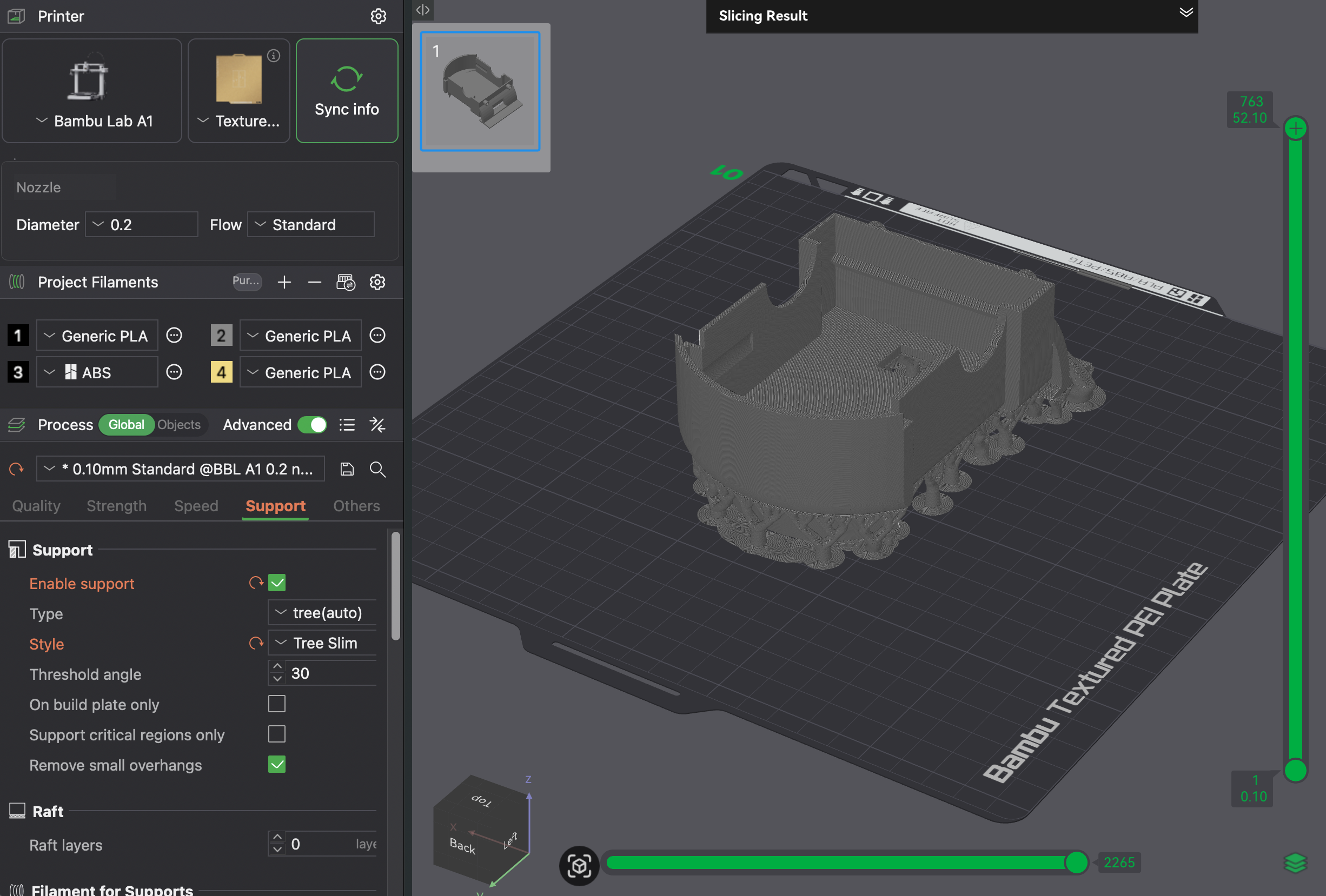
Figure 4.3 (Click the image to view fullscreen)
Settings Print 1-Grey (Figure 4.3):
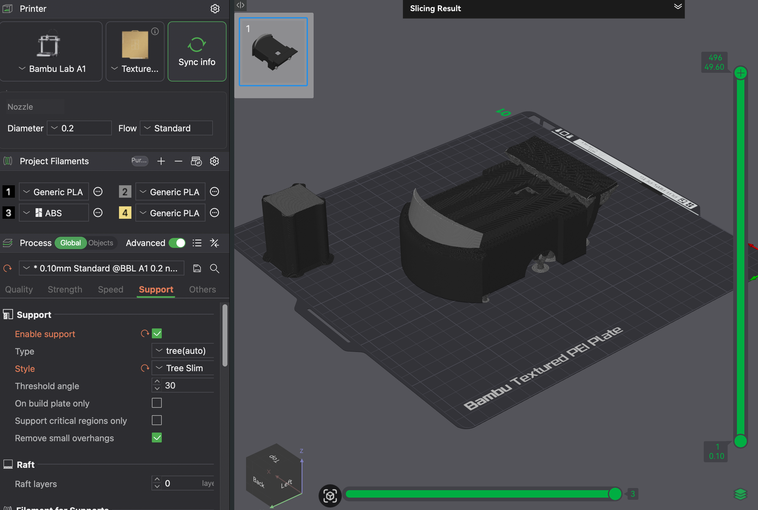
Figure 4.4 (Click the image to view fullscreen)
Settings Print 2-Black/Grey (Figure 4.4):
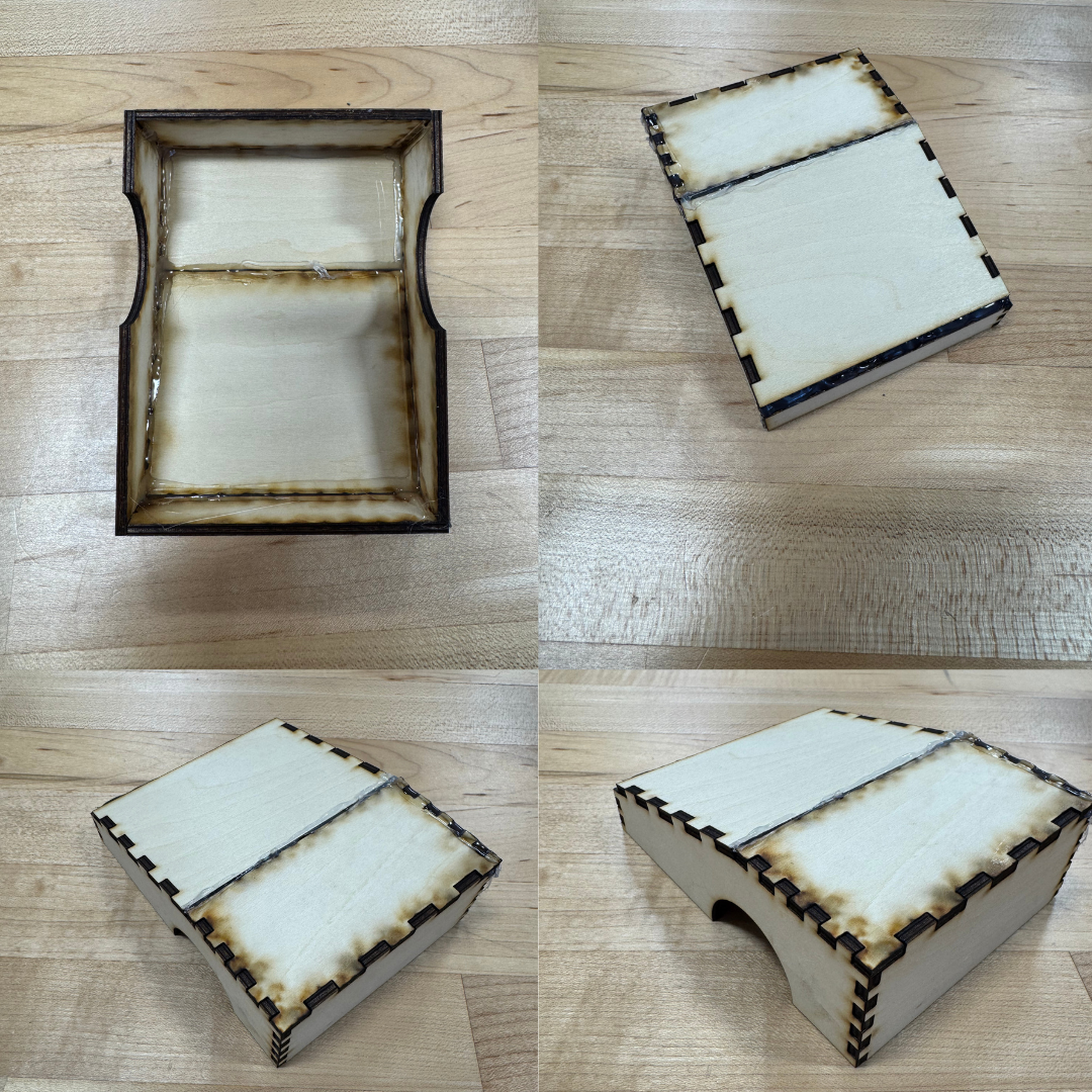
Figure 4.5 (Click the image to view fullscreen)
Laser Cut Chassis
We also created a wooden laser cut, using 3mm plywood sheets. To deisgn our laser cut, we used OnShape to create the three dimensional model, and then used the add-on feature, "auto-layout," to lay each individual face onto the x-plane. Prior to laying the faces flat, we also used the add-on feature, "Laser Joint," which automatically creates a series of joints between two joined, selected edges. This was crucial in benefiting us during assembly, as the parts now fit similiar to a 3D puzzle. The joints also provide further connection support along the face edges, allowing the faces to essentially "rest" on one another. This is superior to flat edges meeting, as there is no connection besides glue in that case. After laying out our completed model, we then exported it in OnShape as a drawing file. This is the desired import file for Light Burn. Below in Figure 4.6, I provide visuals for our drawing in onshape, laser cut settings in Light Burn, and the 3D model.
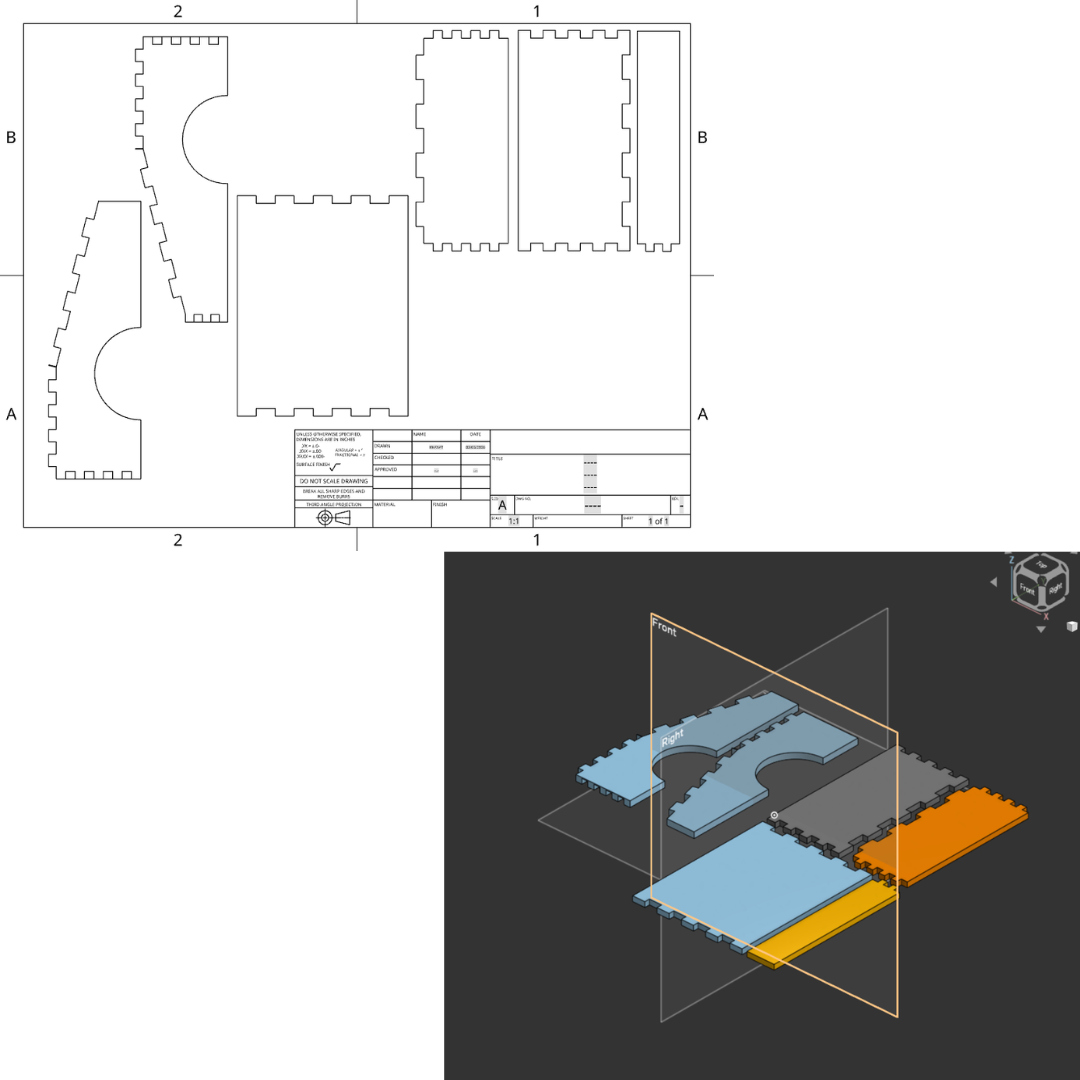
Figure 4.6 (Click the image to view fullscreen)
OnShape Laser Cut Layout (Figure 4.6):
As described above, the auto-layout feature and laser joint feature are apparent in our design pictured in Figure 4.6. Prior to actually making our cut, it is required that all pieces of the model are laying flat, therefore the auto-layout feature saves a lot of time. Laying out each part is critical, as the laser cut is a vertical burn on only the 2D level, unlike a 3D printer with x, y, and z. Post lay out, we exported into a drawing, ensured the dimensions were accurate, imported into Light Burn, and then begin our cut. We also made sure at least one of us was watching the cut as it was going, to check for any signs of fire or toxicity.
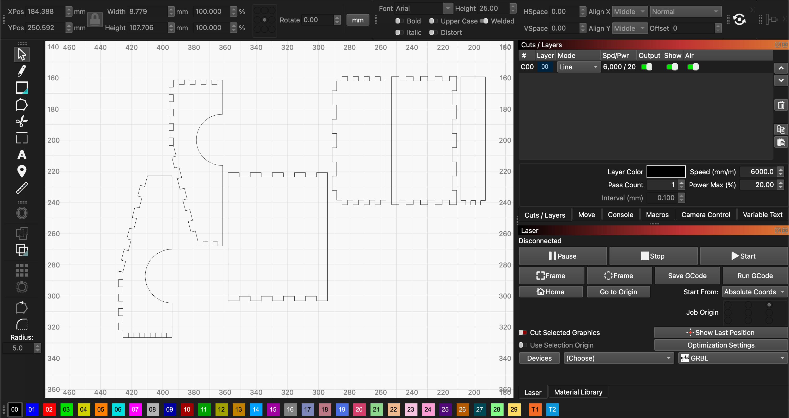
Figure 4.7 (Click the image to view fullscreen)
Settings-Laser Cut (pictured above):
Issues:
Soldering
We had a few issues throughout the process, so I will go through them in order of our approach. Starting with contructing the circuit board, the most time consuming portion was due to having an older soldering iron. The issue is after a while the iron's tip begins to oxidize over time and the more used the iron the more quickly it oxidizes. When this occurs, the solder has a very difficult time heating up and therefore, does not bind to the circuit board or the iron, itself. The consequence of having to re-tin the iron before each solder, slowed us down immensely. On the second day we used a much newer iron, and therefore finished the board quicker and with cleaner solder joints.
3D Prints
Both of our 3D prints were successful; however, there are a few changes I would have made. For the first, grey print, I placed the object upside down in order to avoid using too large of supports, thus decreasing the time. Although this did decrease time, the supports bound to the object too intensely, leaving a "messy" top layer. For our second print, we flipped the object, which avoided the supports on the top, and left a really smooth look. We even got the added benefit of racing stripes, due to an accidently unoticed extrusion in OnShape!
For the second 3D print, we should have also been more careful adding the windshield. When we tilted the shape we added on the top, it extruded through the chassis into the interior cavity. This cause the supports in the front of the cavity to stick, not allowing for them to be fully remove. To avoid this, next time we will be more cautious in removing any unwanted parts.
Laser Cut
Our laser cut went really well, as expected due to the precision of the machine. It printed our joints perfectly as expected, and burned off almost no noticable material, keeping our scale true. The only major downside to the lasercut is the lingering scent of burnt wood, which although easy to remove from our hands, not so easy to remove from the build; limited where a laser cut is desired. For example, you might not want to bring a laser-cut item, made a week ago into an enclosed office space. Overall, my major take away is that laser cutting is superior in speed and precision on basic models, however, for more complex builds, where time is not limited, 3D printing will provide a more complete and detailed model.
e-NABLE Prosthetic Hand
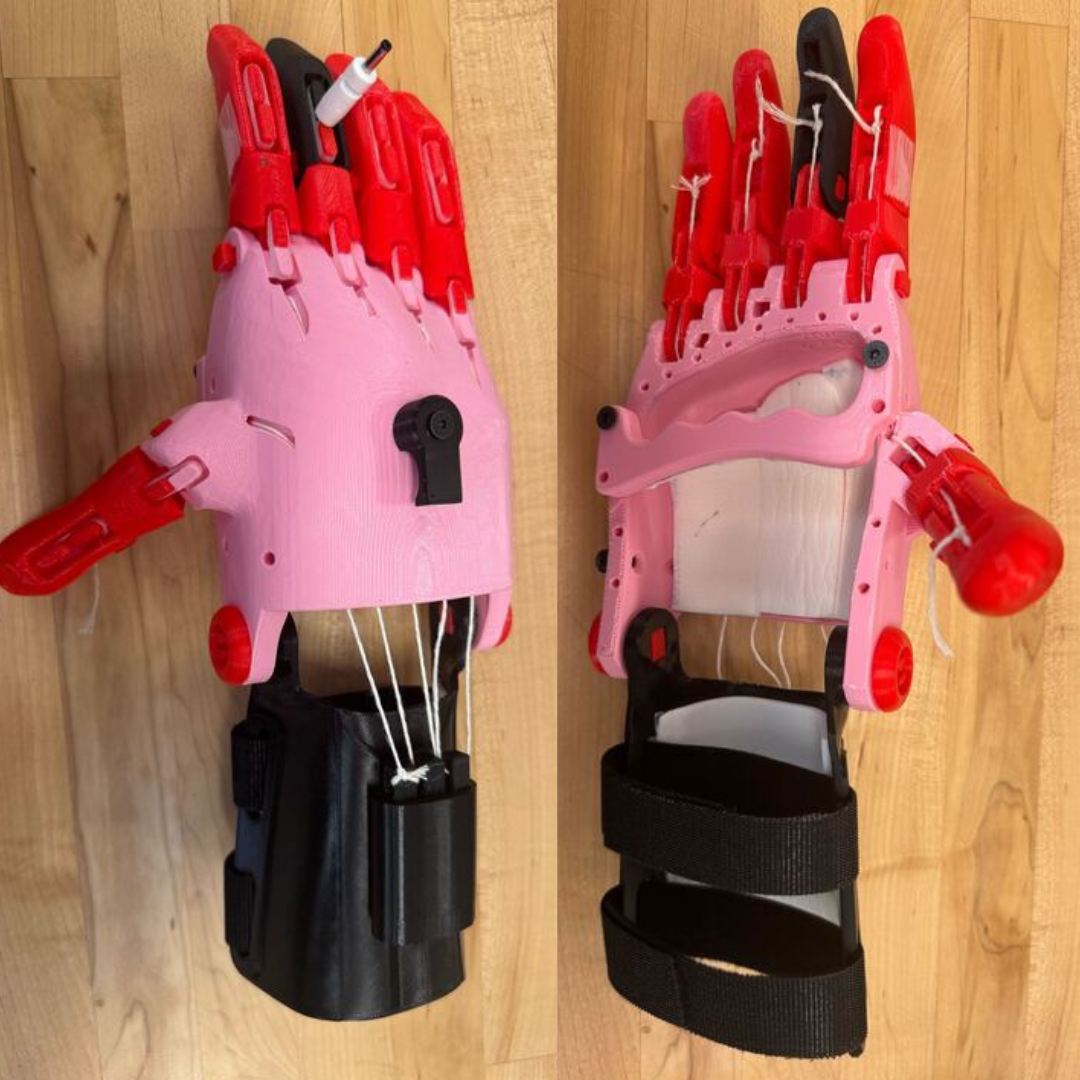
This project was focused on creating a prosthetic device for children. Specifically, my partner Rebecca and I, created a functional hand that allows the user to grasp light-weight objects, as well as, utilize other motor functions they may currently be lacking. The reason for focusing the device towards children, is due to the fact that when a child requires a prosthetic the duration in which the device is created is greater than the growing rate of the child. This results in a device that would be created for an individual, which will most likely no longer fit when ready for shipment. The 3D printed version we created is more simplistic, less costly, and time-conscious. This allows for a product that, although not functionally superior to a normal prosthetic, gives children the opportunity to gain more mobility earlier on. Prior to reading on, it is important to note that ALL prints associated with the creation of the hand itself, not the additions, should be printed at 150% scale from the original files in the resources at the end. I cannot stress enough how beneficial the "Directions Review" section will be for those starting this project from the beginning steps. Please visit that section prior to beginning the build as you will save time, effort, and hopefully recall the focus is always on the end user throughout all steps.
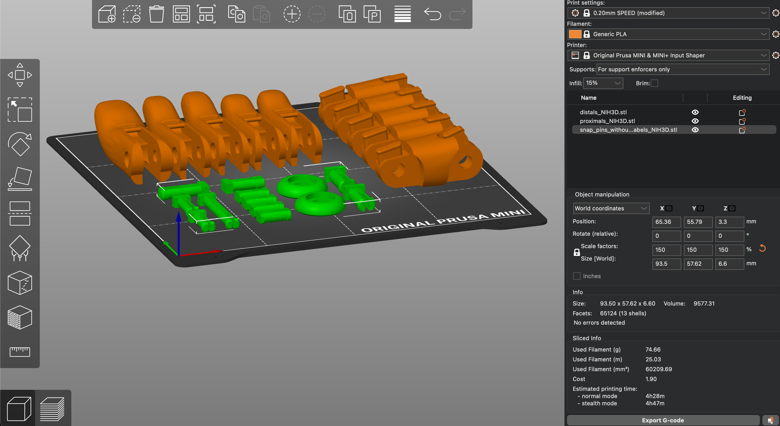
Figure 6.1 (Click the image to view fullscreen)
Settings Digits and Pins (pictured above):
Print Notes:
We printed the device in separate parts, being the digits and pins, palm, and wrist guard with the tension block. Focusing on the digits, we needed to add a "raft" prior to slicing, which stopped any small pieces from disconnecting from the plate. Although the raft was necessary for the digits, the removal of the raft presented it's own challenges which I discuss, in general, further in the issues section and "Directions Review" tab.
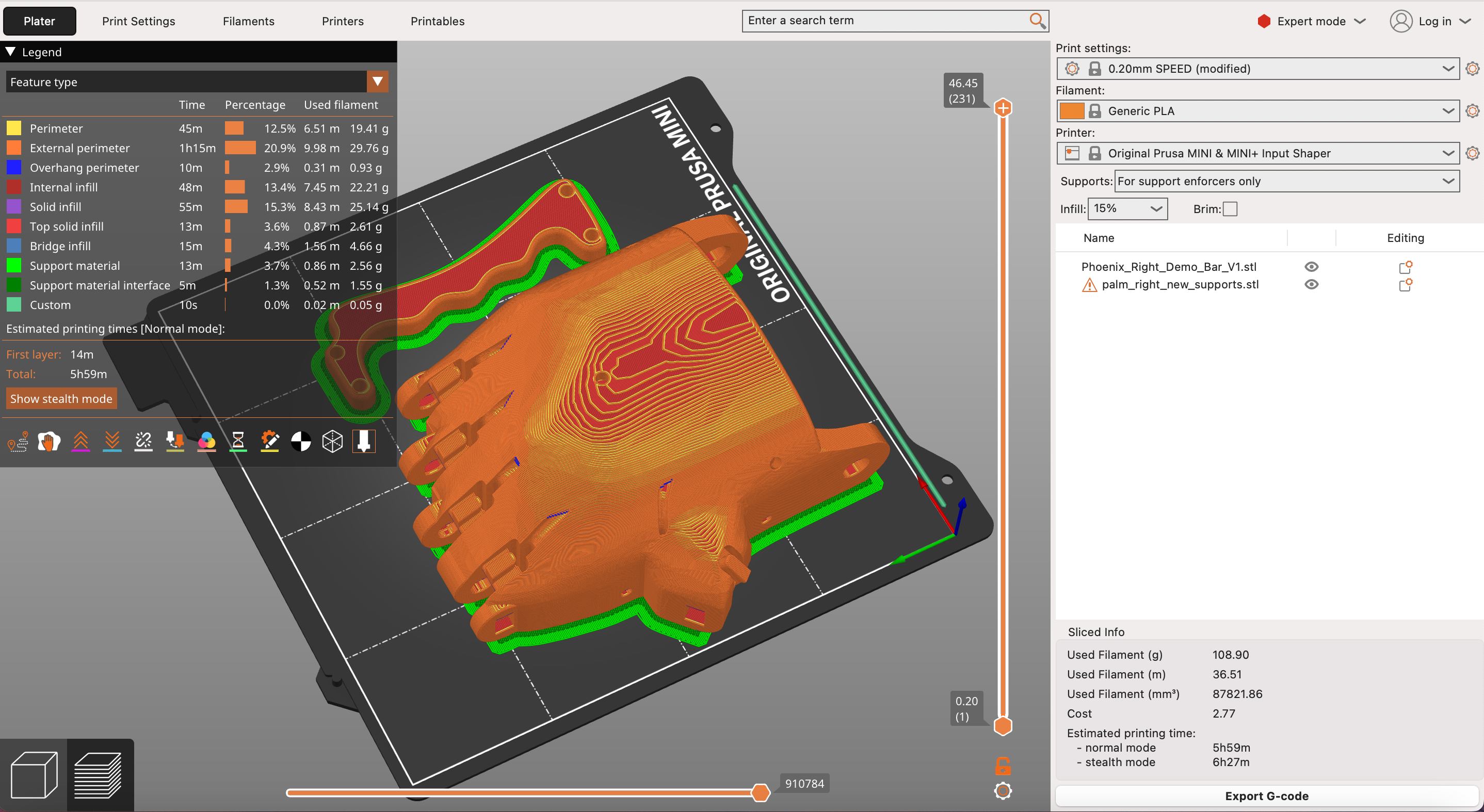
Figure 6.2 (Click the image to view fullscreen)
Settings Palm (pictured above):
Print Notes:
The palm required supports to hold up the cavity where you would insert your appendage. The support was unlike the normal "tree" supports and was a box, which made the removal of supports relatively seamless; not the case with the added raft. We added a raft to the base, similar to the digits, however, it proved unnecessary and even problematic. The raft connected too well to palm which left a lot of jagged edges when removing. We removed these with an exact-o knife, but it added a significant amount of time. To conclude, I would suggest not using a raft for the palm. With the palm, we also printed a bar to go across the inner cavity so my partner and I could test the product. Although, the best way to really test a product, especially one such as a mobility device, is to allow a user with a disability relevant to the device to use it for a while and deliver feedback. Even more impactful, is having that member actually become part of the entire design, testing, and distributing process. Unfortunately, due to time constraints we could not outsource for a member of the team outside of the Maker's space, therefore used the crossbar to attempt to use the device ourselves.
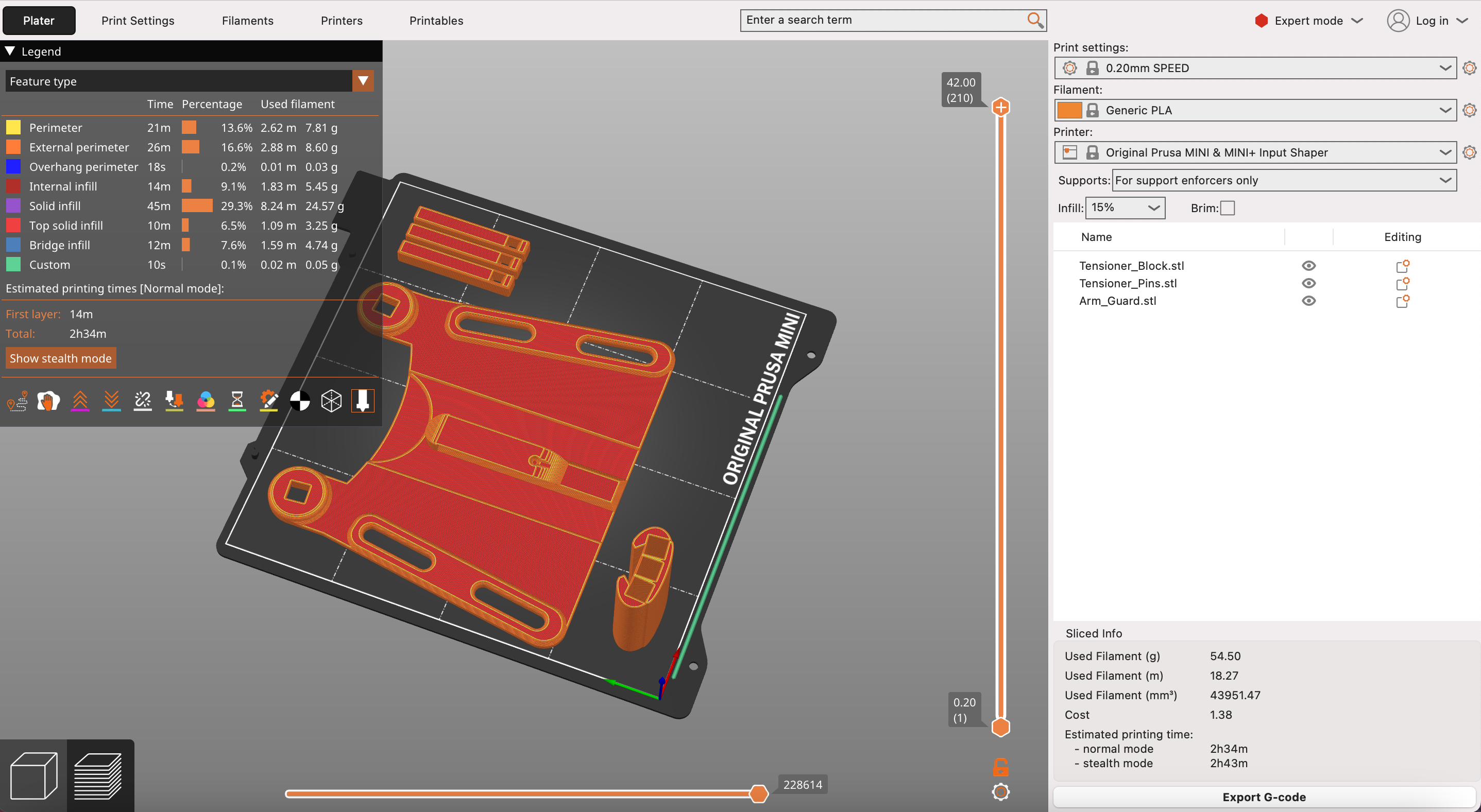
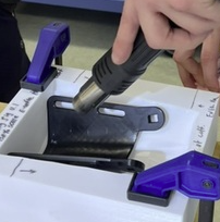
Figure 6.3 (Click the image to view fullscreen)
Settings Wrist Guard(pictured above):
Print Notes:
The palm, pins, and digits are more or less self explanatory in purpose, however when discussing the assembly I will go into further detail about how they operate. The wrist guard and tension block are a bit less intuitive. The tension block is designed to provide the necessary resistance for the device to function properly, acting as an anchor for the wiring. The pins are secured in the block, and wires ran through the hand. In our case, we used string. Obvious from the slicer photo, the guard is not yet properly shaped. In order to form the piece into a proper shape, we used a reflow station attached to a heat gun; shaping the object manually (seen by scrolling through Figure 6.3). This allowed for more customizability, as well as, a cleaner look on the overall print. Shaping after printing also avoids required supports for floating edges, saving time.
Assembly Process
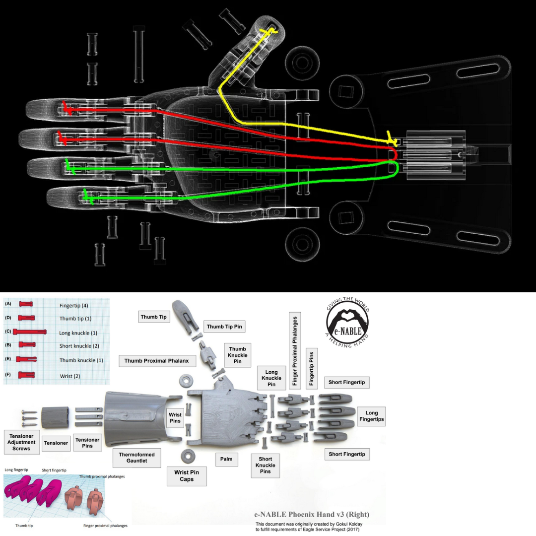
Figure 6.4 (Click the image to view fullscreen)
Prior to beginning our assembly process we watched a video on a similar build but felt it did not focus enough on the orientation of parts, such as the tension block pins, along with lacking detail in regard to the wiring process. We found the images in Figure 6.4 to be the most helpful resources. For one, being detailed images we were not forced to pause a video multiple times to follow any needed instruction. Secondly, the X-ray image displayed the interior wiring structure far better than simplifying watching someone do it themselves. This not only provided clear direction for how to wire our prosthetic, but also allowed us to better understand how the device is going to use tension in order to grasp around objects. Figure 6.5 shows the layout of the components we printed prior to assembly.
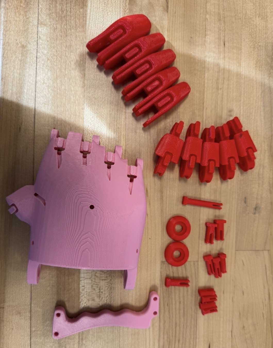
Figure 6.5 (Click the image to view fullscreen)
Adding to the Design
Grocery/Bag Hook and Wire Management
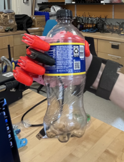
We added three additions to the original design. The first two are exact copies of one another at different scales. The larger hook, mounted on the top of the hand, will provide the user with the ability to freely hold shopping bags and even heavy bottles with a hook to ease the strain on the fingers. The identical hook on the side of the hand provides cable management for the final addition we made. The second hook, was actually a "mistake," in the sense that we did not properly scale the object prior to printing. However, this ended up being a happy accident as we still found a use case for the smaller hook. The main addition can be seen below in Figure 6.6. To avoid cluttering this portion of my description, I added the file for the hook below and a photo to view print settings in Figure 6.6. For scaling purposes, the larger hook is 200% larger than the smaller.
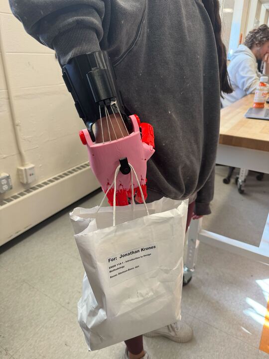
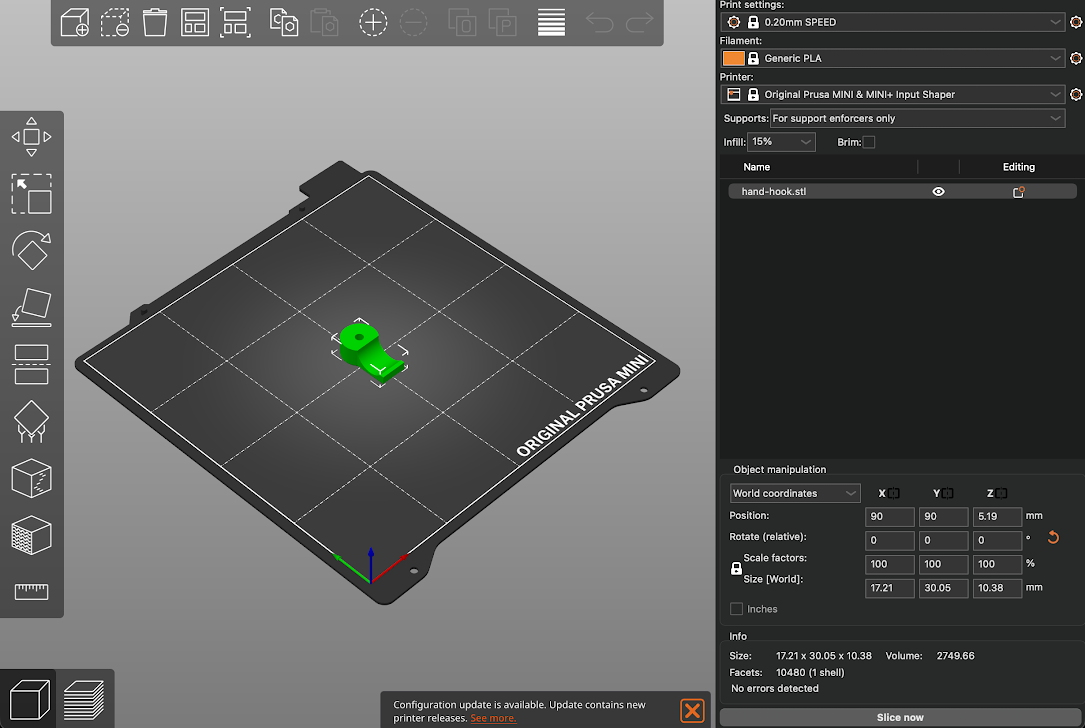
Figure 6.6 (Click the images to view fullscreen)
E.T. Addition
For the final addition we were looking more at the process of combining an electronic with our 3D-print, rather than solving a mobility issue. However, the nature of this addition does solve another problem. We imported one of the fingers into onshape and removed the interior, where the print would be. Then, after extruding a small canal under the region where the strings are, we had a cavity to insert a LED and run a wire through the top of the hand. After two iterations we finally decided on the finger in Figure 6.7. I Included a screenshot of the print settings below, as well as, the file. This was a great way to integrate electronics with our 3D-printed components; given the target audience is children, a "fun" feature such as a light can make the device more enjoyable, and therefore, more likely to be used.
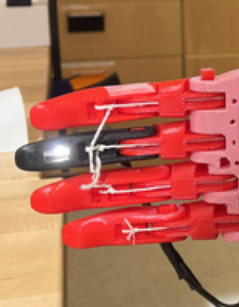
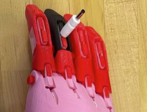
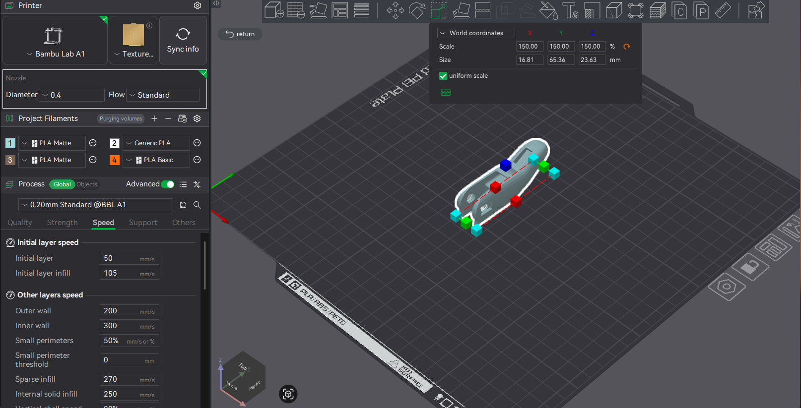
Figure 6.7 (Click the images to view fullscreen)
Issues:
The majority of issues and pitfalls in instruction are found in the Directions Review section, along with a peer review for another group's instructions (which I highly suggest viewing). Although listed in detail under the mentioned section, I'll briefly list a forewarning here:
Links and Resources:
Model used for fingers, pins, wrist guard and tension block components: BioVisUser123. Human Heart Model. Version 2.1, NIH 3D, 2024. Fingers, Pins, Tension Block, Wrist Guard (v3)
Model used for palm: BioVisUser123. Human Heart Model. Version 2.1, NIH 3D, 2024. Palm Only (v2)
X-ray Wire Guide (Scroll through the photos to locate the X-ray wire guide)
Directions Review
At the bottom of the projects page I listed the resources we used to assemble the hand. Throughout our assembly there were various times when we felt there could be improvements on the instructions. Firstly, I would suggest only printing the pins and fingers with a raft. The palm and wrist tension blocks and pins did not need rafts. The process of removing a raft from the palm and crossbar were time consuming and could easily be avoided by opting out of using a raft for certain components. I really enjoyed the peer review below for more information on the rafting! Next issue fell with the screws necessary for assembly. There was not clear mention of which screws to use and after scaling up 1.5x neither an M3 nor an M4 screw fit properly. Along with that fact, the pins also did not properly fit after scaling. I would suggest scaling the pins slightly higher than 150% to ensure a better fit. Referring back to the hardware, using a little bit of force, you can fit an M4 screw. When trying to find the proper tension for the strings, it was more or less a guessing game. Ideally, you want the thumb and pointer to get as close as possible, while allowing to be fully at rest when not in a grip. Again, there was no mention of this in the instructions, however, it was not difficult to figure out. I suggest first tying the string to the fingers and working back towards the tension block. The fingers are much more mobile and therefore are easier to tie up to, first.Finally, I want to touch on the notion we explored in a chapter from the book What Can a Body Do? How we Meet the Built World -Sara Hendren. This chapter focuses on the development of our environment and products relative to the disabled. She mentions the importance of keeping the user in mind when developing such a device. As well as, the necessity to include a user who actually struggles with the disability you are trying to alleviate. I noticed that when constructing this device, there was minimal mention about the disabled user in almost all videos and text outside of that provide by our instructor, Prof. Ian Roy. Prof. Roy perfectly aligned our visions, with the focus that they are practical for real world users. However, this was diverted when created the product, as there was no attention towards the user post-beginning construct. I feel this is important to mention, as we, the makers,must actively connect all portions of the project to a disabled user. This begins with the ideation and follows through into the final steps of testing and distributing. If not thinking of the user during all steps, are we really building the product for them? The answer is no. As mentioned in the projects section, the best strategy is always incorporate the desired user during all steps. An idea Hendren presents quite well.
The idea of incorperating a deesired user during the instructions could not be stressed enough. I find it important to highlight the fact there was no mention of how to assemble this item if you are actually disabled. Although this being a prototype, specifically for anyone to test, someone who may use a finished product in the future would benefit a lot from understanding how to fix or assemble the hand if necessary. Not to mention, when further understanding a product you are given, you can more easily adapt it to your needs.
Peer Review
We also peer reviewed another team, Ben Khayat and Maria Mykhaylyk. I attached their FAQs below to refer to throughout this section. First, the guidance on which exact open source files to use was really helpful because it removes a lot of confusion right away. Knowing to use the Phoenix Hand V2 palm with the V3 fingers and other V3 parts, and to scale everything to 150%. Second, the section on rafts and print settings was very helpful because it gives practical advice that can prevent failed prints. Rebecca andd I used rafts for almost all parts, where Ben and Maria opted out of using a raft for a few portions, which provided a cleaner end result. They also clearly explain which parts need rafts, which do not, and also gives strength tips like using over 25% infill and PETG instead of PLA. Personally, we used PLA, however, I noticed the silk PLA broke on two ddifferent wrist gaurds on two different occasions. Third, the explanation of threading string through the palm using wire stood out as especially useful because it gives a simple, realistic trick that makes assembly easier. We used an alan key and tweezers, which although worked relatively well, a wire will be able to pass through the channels more easily. Overall, I highly suggest reviewing their .pdf prior to even printing. Thank you Ben and Maria!
Directions Revised
This revised direction set is based on the issues we ran into during printing and assembly, along with the strongest strategies we found while completing the hand. The goal is to save future makers time, reduce failed prints, and give back to the community by addressing these issues. Allthough, "Directions Review" touches on some issues, here I more directly mention steps to be most successful.
Files and Scale
Use the Phoenix Hand V2 palm with the V3 fingers, pins, wrist guard, and tension block. Print the full hand at 150% scale. If the connector pins fit too loosely after scaling, reprint only the pins at roughly 155%-158% for better fit.
Print Setup
Print the fingers and pins with a raft because the smaller parts are more likely to disconnect from the plate when the printer is moving. Do not use a raft for the palm, crossbar, wrist guard, or tension block unless absolutely necessary (most likely is not). The palm may still need supports for the inner cavity, but adding a raft there created rough edges, more cleanup, and unnecessary extra time.
Prep Before Assembly
Lay out all printed parts before starting assembly and compare them to a reference image, such as the one I show in Figure 6.4. Use the X-ray wire guide to understand the internal string path and use the parts layout image to identify the major printed components. Videos can be helpful, but in general the X-ray image gives the greatest detail. Before connecting anything, remove leftover raft material and clean rough edges so the joints can move more freely and the device is comfortable to wear.
Pins, Screws, and Fit
Test fit every pin before final assembly. The original hardware guidance was unclear. In our build, an M4 screw fit with some force after the 150% scaling. It is worth checking fit early so you do not need to disassemble later.
String Routing and Tension
Use a thin wire or similar guide to help thread the string through the palm channels. Tie the string to the fingers first, then work backward toward the tension block. Do not fully tighten everything at once. Instead, adjust the tension gradually and test the hand after each added string. The goal is for the thumb and pointer to move close together during grip while still returning to a relaxed position at rest.
Wrist Guard Shaping
After printing, the wrist guard may still need shaping. We used a heat gun attached to a reflow station to manually form the piece into a better curve. I suggest paying close attention to the connection points on the guard to ensure they line up parallel to the palm. This improved the fit and also allowed the part to keep a cleaner look than if we had relied on extra supports during printing. This also allows for post production customizability.
Troubleshooting
If the hand does not return to rest, reduce the string tension slightly. If the grip is too weak, compare the routing to the X-ray guide and tighten in small increments. If finger motion feels blocked, check for rough pin holes, excess raft residue, loose pins, or too much tension. If the palm or crossbar is damaged during raft removal, trim and clean the area first before assuming a full reprint is necessary. You can clean up any jagged edges, but ideally less edges will result in a more comfortable fit.
User Focus
One final revision to the directions is keeping the intended user visible throughout the entire process. As mentioned on the Microsoft Inclusive Design website, recognizing a form of exclusion, via a product, is important to creating assitive devices. However, once this recogniition is made, we should not then abadon the focus on that exclusion. The instructions should not only explain how to print and assemble the device, but also why certain adjustments matter for comfort, function, and accessibility for the person who may eventually rely on the hand.
Line-Tracking Car
This was a joint venture between Ben Khayat and myself in which we explored a few different mediums for constructing a path following kit-car. The vehicle uses two sensors to determine the color change (from bright to dark) of the path and corrects accordingly. The ability to detect these changes, keeps the car focused on the dark electrical-tape path we created.
The kit we used came with all the needed components, including two sensors, motors, wheels, and essential capacitors and resistors (shown in Figure 4.1). We soldered on all the necessary components, which I detailed further below along with certain issues we had. Prior to our build, neither of us had had any experience soldering. The manual (linked here: https://m.media-amazon.com/images/I/A1lEYFXJO1L.pdf) gave thorough instructions with images, however, it did not provide much insight on the soldering process. For example, certain components required different strategies for making the solder joints. The manual, however, wrote all instructions the same regarding "how" to solder the components.
Figure 4.1 (Click the image to view fullscreen)
Constructing The Circuit Board
Prior to constructing the chassis for the car, we needed to solder the parts, shown in the tray above, to the circuit board. We found it helpful to organize our workspace prior to beginning. To best split the work load, we each soldered a few components and then the other would solder an equal amount until we were finished. On the first day, we were using an old soldering iron which downgraded the quality of each solder. In order to combat this, we were constantly tinning and cleaning our iron with iospropyl alchohol. Luckily on day two, we acquired a much newer iron, and therefore had cleaner solders and were no longer required to tin the tip each time. This is apparent in the top right photo in Figure 4.1, by the difference in solder quality. Besides capacitors, LEDs, resistors, components to set the intensity of correction, and other parts for our board, we also had sensors and motors. The sensors allowed for our kit-car to determine the intensity of color on it's left and right sides, which keeps it in line. These sensors would then drive power to either the left motor or right motor depending on what is needed to continue on the dark line. The two LEDs on the front-sides, indicate which wheel is recieving power. The angle of intesity the vehicle will take is dependent on a set of controls that we had to adjust until we were satisfied with the movement. For a turn of too great an angle could send the car off the track and it become "lost." I included a sketch of the dimensions of the board down below.
Figure 4.2 (Click the image to view fullscreen)
Dimensions:
Width (total)=80 mm
Width (interior)=70 mm
Length (total)=110 mm (30mm+80mm)
On/Off Slot=15x15 mm^2
Height= 31mm minimum
Figure 4.2 (Click the image to view fullscreen)
3D Printed Chassis
We decided to create two alternative prints for our project, working together in a shared OnShape space. We shared this responsibilty by adjusting and adding to the project as we both saw fit. The first, being the fully grey print in Figure 4.2, was a focus on scale and fit. In order to determine the proper dimensions for the print we used a caliper to find the length, width, and height of our car. It is important to also pay special attention to the front of the car, which was an arc instead of a flat bumper. By finding the radius of that arc, we easily scaled the front. The first print provided us with confirmation that our dimensions were correct and additions were not outside the realm of our printer's capabilities. This model also ensured we followed the proper guidelines, which allows us to remove the cap to access batteries, provides a small hole for the power button, visibility to LEDs, and free sensors. We printed the first model upside down, to avoid supports in the inner cavity, after ensuring the print preview looked successful by checking the layers in Bambu Studio, we completed version 1.
For our second print, we decided to test multi-filament printing, along with stressing angles to see if it would fail without support. Starting with the angular stress, the windshield is tilted at approximately a 40 degree angle, within the threshold of the print, and therefore succeeded nicely. We also added two faux exhausts on the back to test whether the small exhuast ports would cave-in on itself, it did not! Secondly, we flipped the print, so this time, there were supports holding up the inner cavaity. This provided a cleaner top surface than our first print. Finally, we decided to use two colors to excentuate the windshield and exhausts. Although this increased print time, requiring a filament tower, it also improved the aesthetic and clearly depicts which objects are part of the chassis, itself, and which are existing for visual imrpovement.
Figure 4.3 (Click the image to view fullscreen)
Settings Print 1-Grey (Figure 4.3):
Figure 4.4 (Click the image to view fullscreen)
Settings Print 2-Black/Grey (Figure 4.4):
Figure 4.5 (Click the image to view fullscreen)
Laser Cut Chassis
We also created a wooden laser cut, using 3mm plywood sheets. To deisgn our laser cut, we used OnShape to create the three dimensional model, and then used the add-on feature, "auto-layout," to lay each individual face onto the x-plane. Prior to laying the faces flat, we also used the add-on feature, "Laser Joint," which automatically creates a series of joints between two joined, selected edges. This was crucial in benefiting us during assembly, as the parts now fit similiar to a 3D puzzle. The joints also provide further connection support along the face edges, allowing the faces to essentially "rest" on one another. This is superior to flat edges meeting, as there is no connection besides glue in that case. After laying out our completed model, we then exported it in OnShape as a drawing file. This is the desired import file for Light Burn. Below in Figure 4.6, I provide visuals for our drawing in onshape, laser cut settings in Light Burn, and the 3D model.
Figure 4.6 (Click the image to view fullscreen)
OnShape Laser Cut Layout (Figure 4.6):
As described above, the auto-layout feature and laser joint feature are apparent in our design pictured in Figure 4.6. Prior to actually making our cut, it is required that all pieces of the model are laying flat, therefore the auto-layout feature saves a lot of time. Laying out each part is critical, as the laser cut is a vertical burn on only the 2D level, unlike a 3D printer with x, y, and z. Post lay out, we exported into a drawing, ensured the dimensions were accurate, imported into Light Burn, and then begin our cut. We also made sure at least one of us was watching the cut as it was going, to check for any signs of fire or toxicity.
Figure 4.7 (Click the image to view fullscreen)
Settings-Laser Cut (pictured above):
Issues:
Soldering
We had a few issues throughout the process, so I will go through them in order of our approach. Starting with contructing the circuit board, the most time consuming portion was due to having an older soldering iron. The issue is after a while the iron's tip begins to oxidize over time and the more used the iron the more quickly it oxidizes. When this occurs, the solder has a very difficult time heating up and therefore, does not bind to the circuit board or the iron, itself. The consequence of having to re-tin the iron before each solder, slowed us down immensely. On the second day we used a much newer iron, and therefore finished the board quicker and with cleaner solder joints.
3D Prints
Both of our 3D prints were successful; however, there are a few changes I would have made. For the first, grey print, I placed the object upside down in order to avoid using too large of supports, thus decreasing the time. Although this did decrease time, the supports bound to the object too intensely, leaving a "messy" top layer. For our second print, we flipped the object, which avoided the supports on the top, and left a really smooth look. We even got the added benefit of racing stripes, due to an accidently unoticed extrusion in OnShape!
For the second 3D print, we should have also been more careful adding the windshield. When we tilted the shape we added on the top, it extruded through the chassis into the interior cavity. This cause the supports in the front of the cavity to stick, not allowing for them to be fully remove. To avoid this, next time we will be more cautious in removing any unwanted parts.
Laser Cut
Our laser cut went really well, as expected due to the precision of the machine. It printed our joints perfectly as expected, and burned off almost no noticable material, keeping our scale true. The only major downside to the lasercut is the lingering scent of burnt wood, which although easy to remove from our hands, not so easy to remove from the build; limited where a laser cut is desired. For example, you might not want to bring a laser-cut item, made a week ago into an enclosed office space. Overall, my major take away is that laser cutting is superior in speed and precision on basic models, however, for more complex builds, where time is not limited, 3D printing will provide a more complete and detailed model.
Links and Resources: